Hello OwnTech,
Here is an update of the use of OwnTech Ownverter as a three-phase inverter in the power electronics course at CentraleSupélec, campus of Rennes.
The lab assignment is online at https://éole.net/courses/onduleur/, meant for 4 sessions of 3 hours, with the following topics:
- DC/DC conversion (1 session, see previous message). Goal is:
- getting familiar with the hardware + witness core phenomena in power electroncis: relation between duty cycle and average voltage (Vout = Vin*duty), current ripple (function of L, duty cyle and not yet switching frequency due to Power API bug)
- Islanded inverter (1 session, autonomous, open loop voltage source): understand again the link between duty cycle and average output voltages, but now in a three-phase AC context. E.g. the need to add a 50% offset to the duty cycle. And the the max AC voltage amplitude being Vdc/2 (not using Space Vector Modulation in such an introductory course). This is where we uncovered the glitch when duty cycle reaches 0% or 100% (dedicated thread)
- Grid connected inverter (2 sessions), with first a focus on grid synchronization using an SRF PLL. Perhaps the focus on PLL was a bit too strong so that there was little time left for grid connected operation (grid following current control as reported in Oct 2025 message.
For programming the microcontroller of OwnVerter boards, students start with working or almost working code. To avoid students having to deal with Git branches and to allow them to keep previous code untouched, I chose to instruct them to clone a different repo for each session, which make for a total of 4 (which under the hood share many common commits):
- DC/DC https://github.com/pierre-haessig/ownverter-dcdc
- Islanded inverter: https://github.com/pierre-haessig/ownverter-islanded
- Inverter with PLL, but feeding an islanded load: https://github.com/pierre-haessig/ownverter-sync
- Grid connected inverter https://github.com/pierre-haessig/ownverter-grid (very close to the previous one, just adding PI for current)
Almost working code means that students have at most a few line to edit. and even this small amount requires a careful monitoring (e.g. one group spending more than half their experiments with a wrong inveter phase shift because in C/C++, 2/3*PI is not equal to 2*PI/3… I should have requested a more thoroughful check of their inverter voltages).
Notice that for people who just want to use these code with no needs for edits, repos include a “secret” branch called completed… GitHub - pierre-haessig/ownverter-sync at completed
Improved embedded scope
Starting with the Inverter+PLL, using the embedded scope is needed. I’ve modified the original ScopeMimicry to fix some bugs and improve some aspects. In particular, a time vector is recorded.
Part of this work is awaiting merge to the original repo (scopemimicry PR #6), but some is only in my repo (it’s breaking a bit the API).
Also, I have some further ideas to improve the host side (Python code which receives and plot the data), yet to be implemented. My vision is that:
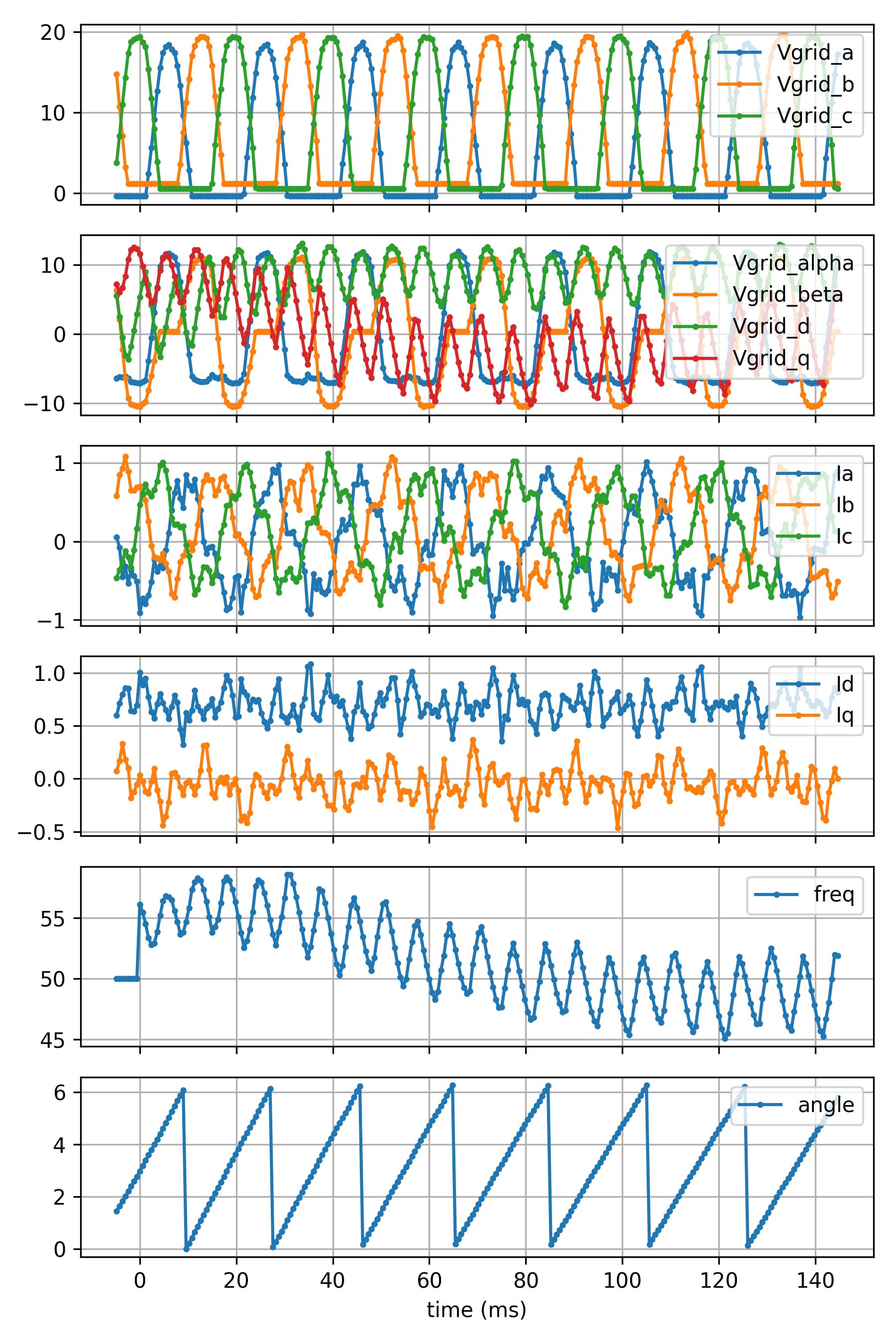
users should be able to configure the plot layout from a simple declarative file living close to the platformio.ini or src/main.cpp. For the moment the plot layout is hardcoded in the Python script (scope record monitor filter). Here is an illustration for PLL synchronization over 150 ms:
Feedback from the field
Overall, these 4 sessions proved that OwnTech Ownverter is a versatile platform for power electronics lab (one board for basic introductary DC/DC up to AC grid connected inverter). At first I feared that the VS Code+PlatformIO config would be complicated to set up in a restricted IT environment (no persistent user sessions!), but with some tweaks it worked! This is very positive.
One basic thing to be improved: the need to reset the board when Upload fails (or said simpler: upload shouldn’t fail ![]() ). In some sessions, board reset was needed more than 10 times per board! Also, the reset procedure itself is complicated (a two button hold + release one + release the other procedure). While creating the codes, I didn’t encountered that many upload fails. Perhaps a Linux vs Windows difference?
). In some sessions, board reset was needed more than 10 times per board! Also, the reset procedure itself is complicated (a two button hold + release one + release the other procedure). While creating the codes, I didn’t encountered that many upload fails. Perhaps a Linux vs Windows difference?
Next steps
- create a minimal box to hold the board along the inductive filter + banana plugs (as opposed to the existing open wire connection
- perhaps add a Vdc/2 pull up to avoid the 0V saturation of negative grid voltages (see PLL sync capture above)
- perhaps add some capacitive filtering,
- for measurements, as experimented during the October HackµLoop hackathon?*
- for power as well?