Hello,
Here is the three-phase duty cycle computation code, where v_angle is the phase angle (in [0, 2PI]) which is incremented at each control step:
if (v_angle <= PI) duty_a = 1.0;
else duty_a = 0.0;
if (ot_modulo_2pi(v_angle - 2.0/3.0*PI) <= PI) duty_b = 1.0;
else duty_b = 0.0;
if (ot_modulo_2pi(v_angle - 4.0/3.0*PI) <= PI) duty_c = 1.0;
else duty_c = 0.0;
With this code, I indeed get the nice fixed levels current which are typical of three-phase square wave inverter . However, the voltage isn’t clean of switchings. It’s as if the duty is not exactly 0. but perhaps some small > 0 value (or slightly <1.0 value).
So my questions are:
in the underlying shield.power.setDutyCycle(LEG1, duty_a) function, is there some adjustment which prevents using duty = 0.0 and/or 1.0 ?
Is there a better approach to fix leg switch state UP or DOWN?
Are you using the last version of core ?
committed 09:26AM - 26 May 25 UTC
**Description**
This PR is a major overhaul of the HRTIM that addresses multipl… e issues:
- #120
- #113
- #110
- #105
- #72
I have also added the necessary comments to answer
- #54
This PR also uses all that was proposed in the
- #74
---------
Co-authored-by: Luiz Villa <[email protected] >
This commit introduced the possibility of having full 100% and full 0% PWM.
I think your are looking for this function :
Let me know if it helps
Thanks for the feedback. About the Core version I’m using, I suppose it’s fine because my repo is a fork of commit commit 73f15dd (July 11, 2025) (fork in the crude sense of starting a fresh repo from the workspace files of another…)
What I don’t understand is: what is the default value of min and max limits of the duty cycle, before calling setDutyCycleMin/Max
Because in the BLDC example I took inspiration from, there is no call to these in the setup routine. Or is it hidden in a static app configuration file?
EDIT:
in relation to the question of the default duty cycle bounds, I see that the docstring of setDutyCycle states in the parameters description:
duty_value The duty cycle value to set (a floating-point number between 0.1 and 0.9).
Hello @pierre-haessig ,
Indeed, the default values of duty cycle are:
Vduty MIN = 0.1
Vduty MAX = 0.9
You can use the function below for instance to set the value to zero.
shield.power.setDutyCycleMin(LEG1,0.0)
Should we add explicitly somewhere that the min and max are 0.1 and 0.9 ?
Thanks for both feedbacks.
I have added the call to setDutyCycleMin and Max in my three-phase islanded inverter application GitHub - pierre-haessig/ownverter-islanded at completed (using the completed branch, since main is the student version with a few blanks to be filled.)
This unlocks the ability to use extreme duty cycle values. However, this led to the following issues which I only reported today
opened 10:31AM - 03 Dec 25 UTC
bug
documentation
enhancement
# [HRTIM ?] PWM glitches when using extreme duty cycle values 0.0 and 1.0
Nov-D… ec 2025
Using the Ownverter 1.1 board, with 1.0 Power API code, there are glitches when using duty cycle values equal or close to 0.0 or 1.0.
Here are two cases, with slightly different symptoms. Both were created using three-phase islanded inverter application https://github.com/pierre-haessig/ownverter-islanded/tree/completed (using the `completed` branch, since main is the student version with a few blanks to be filled.)
- sinusoidal duty cycles PWM
- square wave modulation
In all cases, experimental conditions are: three-phase inverter connected through an inductive filter (630 µF) to either a balanced R=10Ω load or R+L load (L=76 mH).
In all cases, the control task period is 0.1 ms = 100 µs (10 kHz)
## Sinusoidal duty cycles PWM
In this application, with pure R load, the duty cycles are [computed](https://github.com/pierre-haessig/ownverter-islanded/blob/completed/src/main.cpp#L291) as:
```Cpp
duty_a = duty_offset + duty_amplitude * ot_sin(v_angle);
duty_b = duty_offset + duty_amplitude * ot_sin(v_angle - 2.0/3.0*PI);
duty_c = duty_offset + duty_amplitude * ot_sin(v_angle - 4.0/3.0*PI);
```
with `duty_offset` set to 0.5 and `duty_amplitude` set to 0.5, so that the duties reach 0 or 1 once per electric period (50 Hz/20 ms).
Here are the resulting oscilloscope captures, with incremental zoom around the top of the sinusoid:
- yellow-(C1): inverter voltage (phase to PGND or phase to Neutral, I don't remember)
- pink (C2): current through load
- green and cyan (C3, C4): swiching signals (CHA1 and CHA2 pins)
|  |  |
| ------------------------------------------------------------ | ------------------------------------------------------------ |
|  |  |
Observations:
- the sinusoidal current is heavily perturbed 6 times per period, in fact each time one of the three phases has its duty cycle close to 0 or 1.
- zooming to the top of the sinusoid, we see that the glitches corresponds to undue switchings while the PWM output should stay constant.
- the switchings happen at integer multiple of the control period (100 µs), so that they are linked to calls to [setDutyCycle](https://github.com/pierre-haessig/ownverter-islanded/blob/completed/src/main.cpp#L331), with changing values of duty
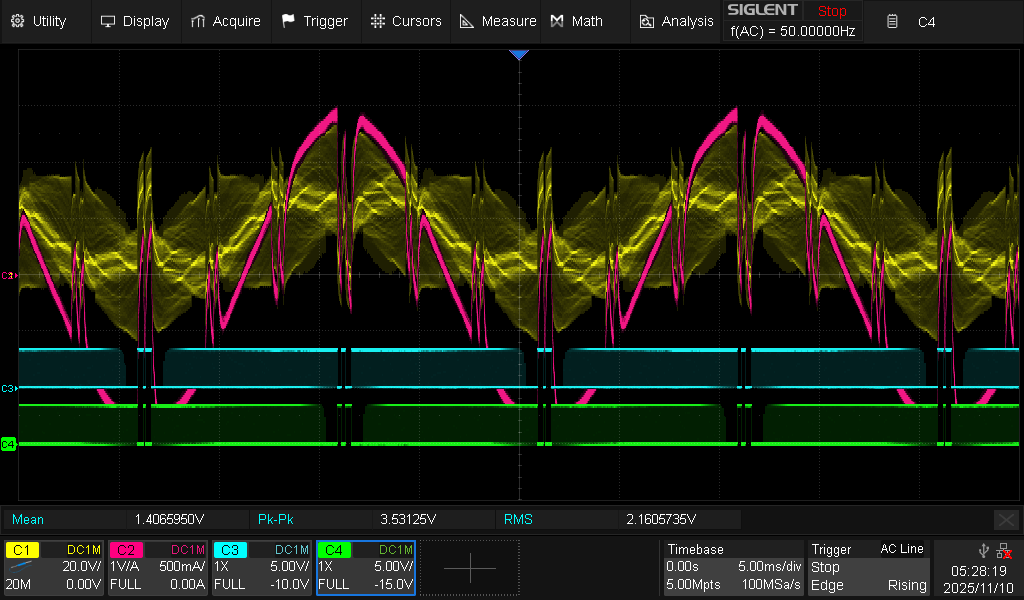
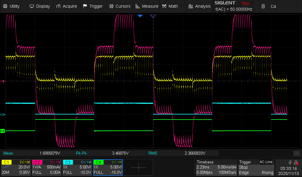
## Square wave modulation
The square wave modulation is done by [setting the duty cycle to 0.0 or 1.0 on appropriate half periods](https://github.com/pierre-haessig/ownverter-islanded/blob/completed/src/main.cpp#L296):
```Cpp
if (square_wave) {
if (v_angle <= PI) duty_a = 1.0;
else duty_a = 0.0;
if (ot_modulo_2pi(v_angle - 2.0/3.0*PI) <= PI) duty_b = 1.0;
else duty_b = 0.0;
if (ot_modulo_2pi(v_angle - 4.0/3.0*PI) <= PI) duty_c = 1.0;
else duty_c = 0.0;
}
```
The resulting oscilloscope captures are obtained here with a pure R load (still with L filter, so that L/R = 63 µs).
Results are even more suprising than with sine PWM.

| Zoom around a half period switch point | Zoom around a constant duty region |
| ------------------------------------------------------------ | ------------------------------------------------------------ |
|  |  |
|  | |
|  |  |
|  |  |
Observations:
- despite the fact that the duty is kept constant, there almost are periodic glitches (every 300 to 400 µs)
- it doesn't seem periodic with the control task
- even more surprising, **no glitch is visible on the PWM output** (CHA1 and CHA2 pins) which are constant!
There are issues in two cases:
sinusoidal duty cycles PWM
square wave modulation (only using d=0.0 or d=1.0)
with variants between the two cases:
sinusoidal duty cycles PWM: glitch is visible in the pwm signal (CHA1 and CHA2), so that an HRTIM issue is likely
square wave modulation: glitch is not visibile in the pwm signal, but still in the current and voltages. So perhaps the problem is not with HRTIM
Sinusoidal case:
Square wave case:
Hello @pierre-haessig ,
The issue was a little deeper. I explain it in detail inthis pull request .
The TLDR is that the 1/0 takes place after a comparison, and the value of the comparison was wrong. I updated it. It should work seamlessly now.
Please:
add my fork of the Core to your VSCode git graph,
checkout my branch ,
put your main.cpp code in it and
put the results here
Thanks @luiz_villa for starting fixing the issue. I’ve updated the PR with test results which is mostly negative: your patch has an effect, but not enough to fix the issue
opened 10:31AM - 03 Dec 25 UTC
bug
documentation
enhancement
# [HRTIM ?] PWM glitches when using extreme duty cycle values 0.0 and 1.0
Nov-D… ec 2025
Using the Ownverter 1.1 board, with 1.0 Power API code, there are glitches when using duty cycle values equal or close to 0.0 or 1.0.
Here are two cases, with slightly different symptoms. Both were created using three-phase islanded inverter application https://github.com/pierre-haessig/ownverter-islanded/tree/completed (using the `completed` branch, since main is the student version with a few blanks to be filled.)
- sinusoidal duty cycles PWM
- square wave modulation
In all cases, experimental conditions are: three-phase inverter connected through an inductive filter (630 µF) to either a balanced R=10Ω load or R+L load (L=76 mH).
In all cases, the control task period is 0.1 ms = 100 µs (10 kHz)
## Sinusoidal duty cycles PWM
In this application, with pure R load, the duty cycles are [computed](https://github.com/pierre-haessig/ownverter-islanded/blob/completed/src/main.cpp#L291) as:
```Cpp
duty_a = duty_offset + duty_amplitude * ot_sin(v_angle);
duty_b = duty_offset + duty_amplitude * ot_sin(v_angle - 2.0/3.0*PI);
duty_c = duty_offset + duty_amplitude * ot_sin(v_angle - 4.0/3.0*PI);
```
with `duty_offset` set to 0.5 and `duty_amplitude` set to 0.5, so that the duties reach 0 or 1 once per electric period (50 Hz/20 ms).
Here are the resulting oscilloscope captures, with incremental zoom around the top of the sinusoid:
- yellow-(C1): inverter voltage (phase to PGND or phase to Neutral, I don't remember)
- pink (C2): current through load
- green and cyan (C3, C4): swiching signals (CHA1 and CHA2 pins)
|  |  |
| ------------------------------------------------------------ | ------------------------------------------------------------ |
|  |  |
Observations:
- the sinusoidal current is heavily perturbed 6 times per period, in fact each time one of the three phases has its duty cycle close to 0 or 1.
- zooming to the top of the sinusoid, we see that the glitches corresponds to undue switchings while the PWM output should stay constant.
- the switchings happen at integer multiple of the control period (100 µs), so that they are linked to calls to [setDutyCycle](https://github.com/pierre-haessig/ownverter-islanded/blob/completed/src/main.cpp#L331), with changing values of duty
## Square wave modulation
The square wave modulation is done by [setting the duty cycle to 0.0 or 1.0 on appropriate half periods](https://github.com/pierre-haessig/ownverter-islanded/blob/completed/src/main.cpp#L296):
```Cpp
if (square_wave) {
if (v_angle <= PI) duty_a = 1.0;
else duty_a = 0.0;
if (ot_modulo_2pi(v_angle - 2.0/3.0*PI) <= PI) duty_b = 1.0;
else duty_b = 0.0;
if (ot_modulo_2pi(v_angle - 4.0/3.0*PI) <= PI) duty_c = 1.0;
else duty_c = 0.0;
}
```
The resulting oscilloscope captures are obtained here with a pure R load (still with L filter, so that L/R = 63 µs).
Results are even more suprising than with sine PWM.

| Zoom around a half period switch point | Zoom around a constant duty region |
| ------------------------------------------------------------ | ------------------------------------------------------------ |
|  |  |
|  | |
|  |  |
|  |  |
Observations:
- despite the fact that the duty is kept constant, there almost are periodic glitches (every 300 to 400 µs)
- it doesn't seem periodic with the control task
- even more surprising, **no glitch is visible on the PWM output** (CHA1 and CHA2 pins) which are constant!