Hello,
Here is a short update about my experiments with OwnVerter used as a three phase grid connected current controlled converter (i.e. grid following).
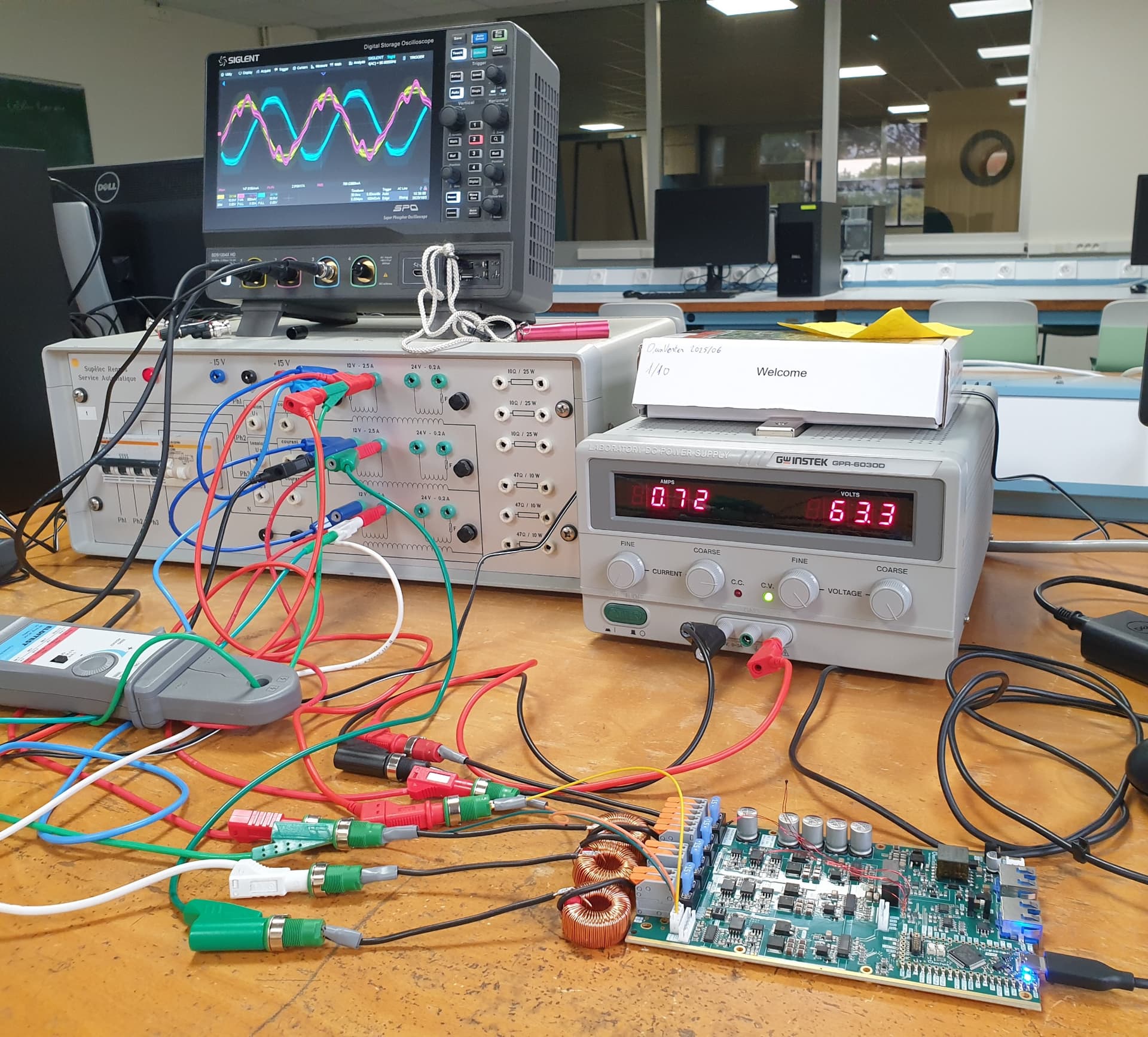
Just to let you know that, after much hardware and software debugging (*), the converter is finally injecting power back to the actual campus grid! (through a 15V transformer). Power injection tested at about 30 – 45 W (1A current injection amplitude).
The hardware is OwnVerter board tied with a crude inductive filter (three 630µH WE-SI inductances which are supposedly suited for up to 100 kHz switching frequency… OwnVerter is only at twice this value). DC source is a 60 V DC power supply.
The converter follows the Id/q current setpoint with the expected transient convergence (closed loop time constant set to 5ms or 20ms).
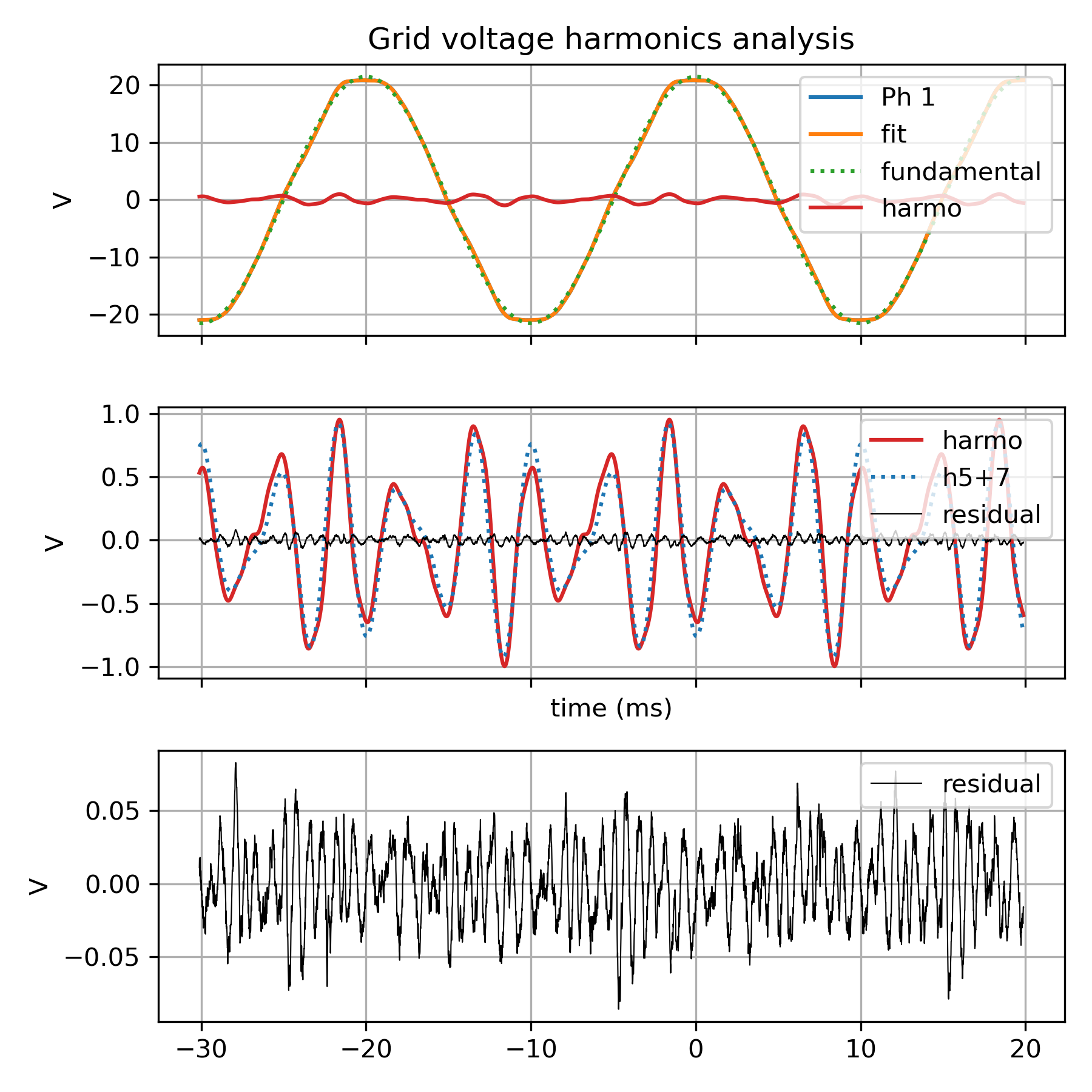
The most striking control defect is the presence of a quite large harmonic current perturbation (probably harmonic 5, perhaps 7 as well). The current control design is not equipped to reject harmonic disturbances and I suspect that the grid voltage has a few percents of odd harmonics, enough a quantity to explain the harmonic current of about 0.2 A.
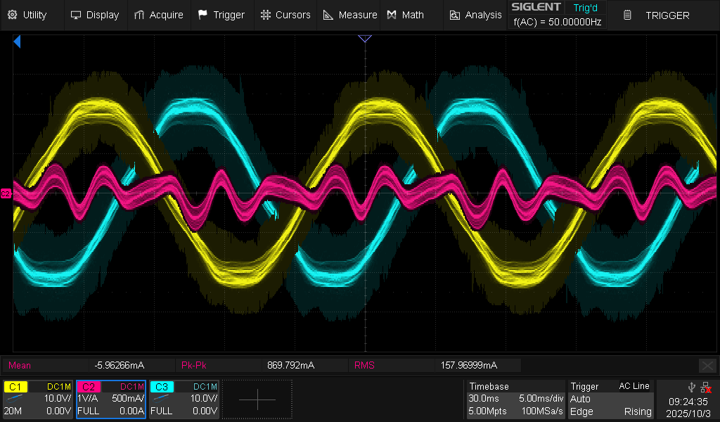
Scope capture (1A setpoint. Yellow: Ph1 grid voltage, Pink: Ph1 Current, Cyan: Ph2 grid voltage)
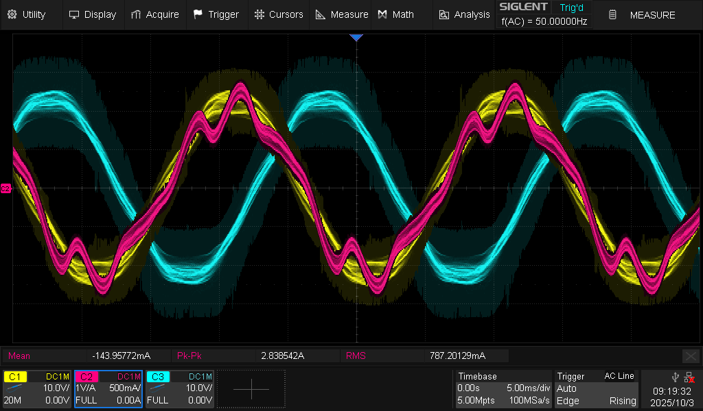
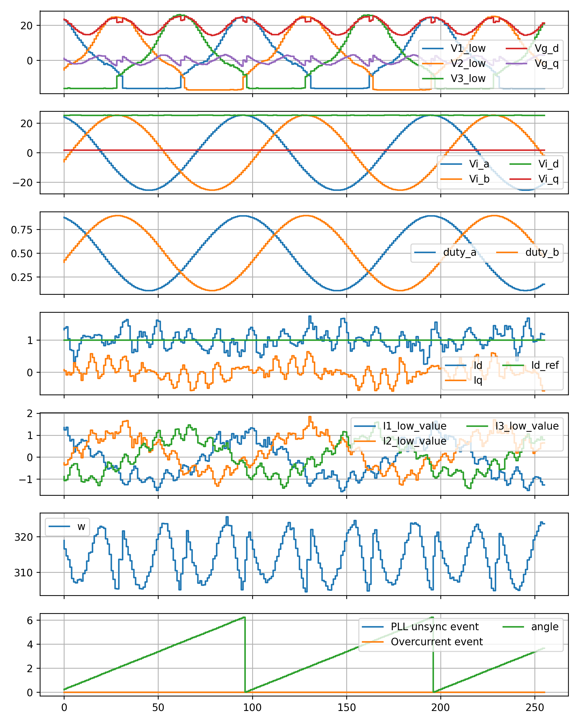
Same situation seen from the board. The current is quite noisy. Also grid voltage (phase to DC-) has a pretty awkward shape, but the PLL is robust/slow enough to handle this as a harmonic perturbation.
Thanks to OwnTech team for all the useful discussions in the last weeks!
(*) bug examples: flipped lower and upper bounds for PI control ⇒ 0 V output ![]() , flipped phase order, or wrong PI control tuning formula…
, flipped phase order, or wrong PI control tuning formula…