Automated Switching Loss Measurement Bench – Open Science Collaboration
Over the past months, we have developed an open-source automated test bench dedicated to switching loss characterization using the opposition method.
This effort emerged from a two-day hackathon, followed by monthly “Open Power Tuesday” sessions, gathering contributors from LAPLACE, LAAS, OWNTECH Foundation, NXP, and others.
![]() GitHub Repository: link_here
GitHub Repository: link_here
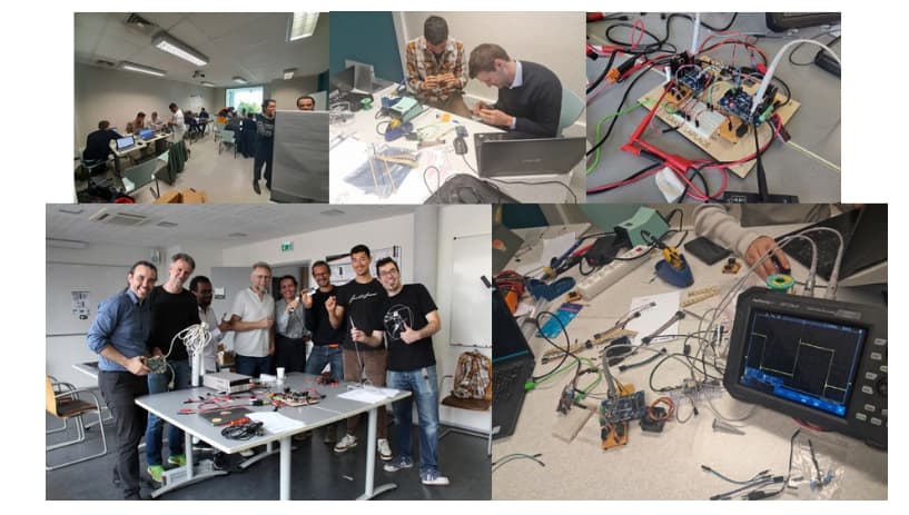
Figure 1 - All the work we’ve been putting into this project since April 2024
 Objective
Traditional double-pulse tests are widely used for switching loss measurement, but they lack flexibility for fully automated multi-parameter sweeps.
The opposition method offers:
- Higher precision through steady-state energy balance
- Indirect but more representative measurements
- Challenges: thermal rise, synchronization, multi-device coordination
Our goal was to fully automate this method using only open tools, from signal generation to instrumentation control and post-processing.
 System Architecture
The bench is composed of three main layers:
- Python Supervisor & Instrument Control (via SCPI / PyVISA)
- Microcontroller-Based Command Generation (OwnTech SPIN / 5.4 GHz clock sync)
- Power Hardware – Opposed Half-Bridge Cells with Isolated Drivers
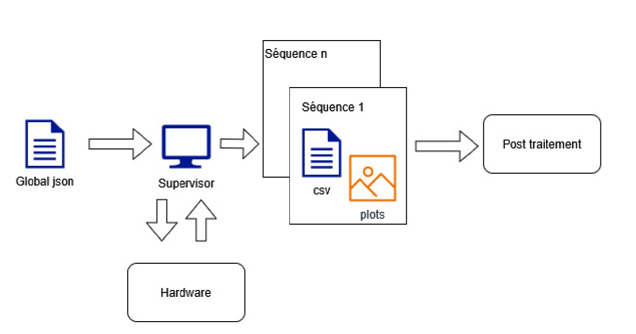
Figure 2 - System software architecture (still in French)
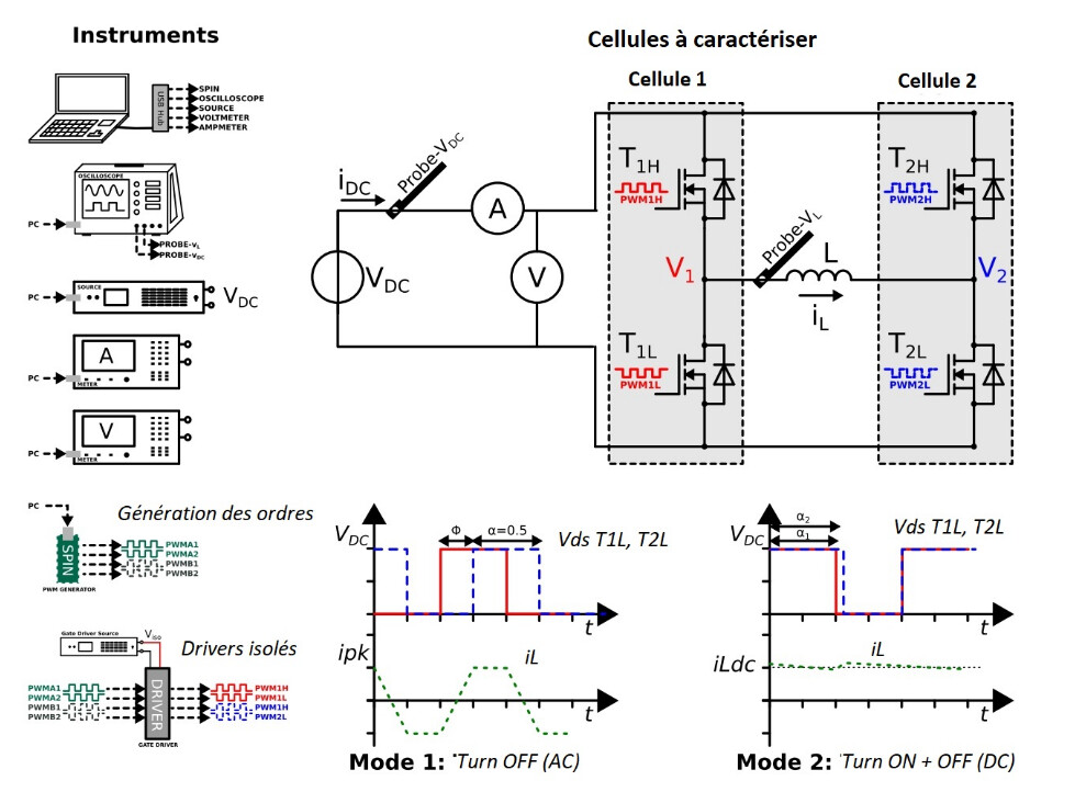
Figure 3 - Test bench architecture (still in French though)
 Current Capabilities
![]() Automated sweep of:
Automated sweep of:
- DC bus voltage
- Phase shift between cells
- Duty cycle offset
- Switching frequency
![]() Synchronized triggering with hardware sync pulse
Synchronized triggering with hardware sync pulse
![]() Fast segmented memory acquisition on oscilloscope
Fast segmented memory acquisition on oscilloscope
![]() JSON-based experiment configuration
JSON-based experiment configuration
![]() GUI available for validation and manual runs
GUI available for validation and manual runs
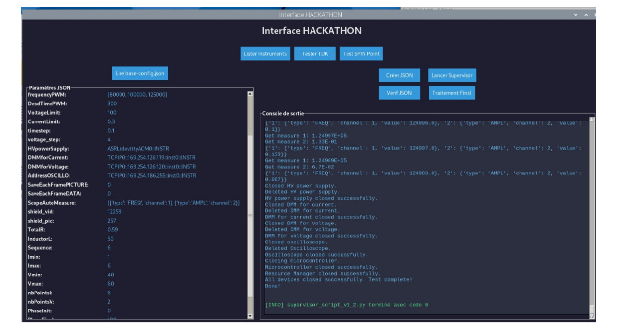
Figure 4 - Our GUI
 Hardware Implementation
We used Infineon EVAL-1ED3122Mx12H half-bridge evaluation boards, initially delivered without power MOSFETs or isolated supplies.
During the hackathon:
- Components were selected and soldered manually
- A 48 V Si MOSFET configuration was validated first
- Later sessions upgraded to higher voltage and thermally improved builds
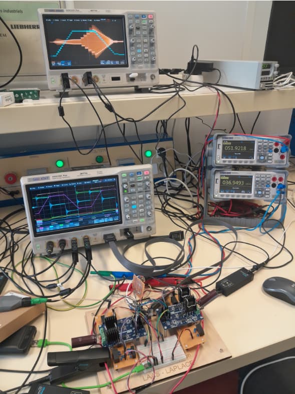
Figure 5 - Overview of the global test bench
 Experimental Results
The bench is already delivering fully automated switching energy measurements.
- Opposed cell control allows separation of turn-on and turn-off losses
- Energy during switch-off vs Current and Energy vs Voltage curves are now automatically extracted
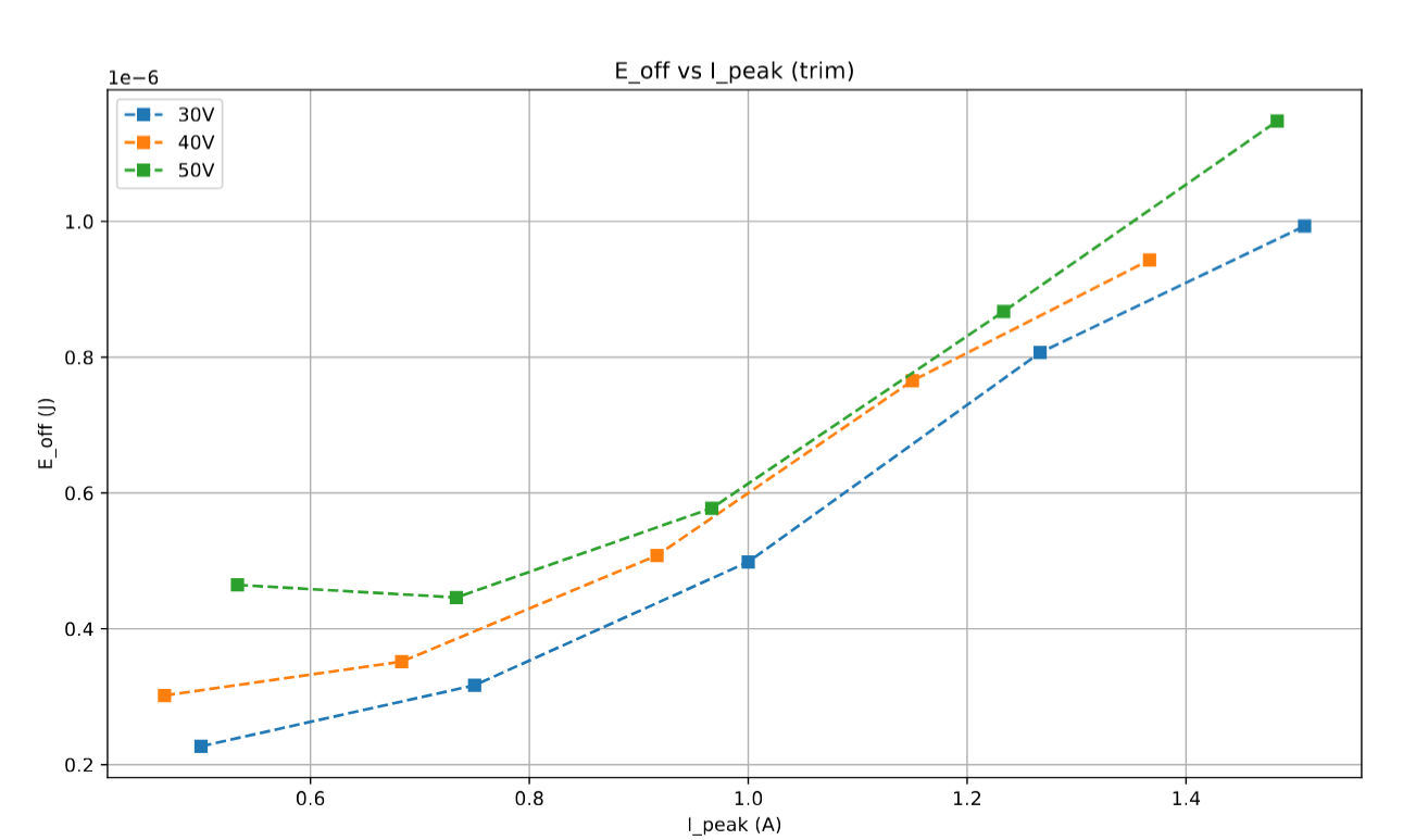
Figure 6 - Switch off energy for : 5 different peak current levels and 3 different bus voltage levels
Additional captures illustrate phase-shift vs duty-ratio modes:
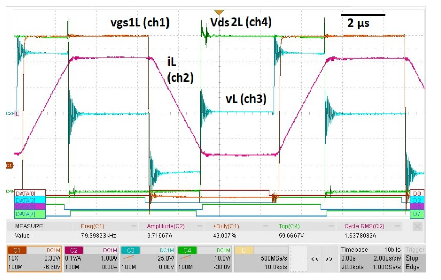
Figure 7 - Main operating signals over one switching period (phase-shift mode). Parameters: 60 V bus voltage, 80 kHz switching frequency, 50 µH inductance, 150° phase shift, 300 ns dead time.
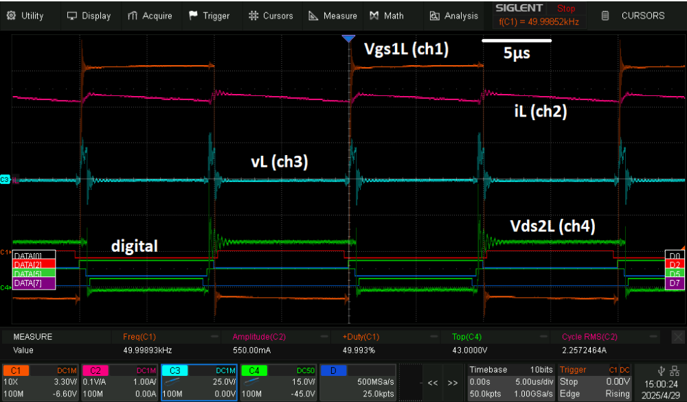
Figure 8 - Main operating signals over one switching period (duty-cycle offset mode). Parameters: bus voltage reduced to 30 V, switching frequency of 50 kHz, 50 µH inductance, 300 ns dead time, 0.8 % duty-cycle mismatch.
 Next Steps & Call for Collaboration
Here are the next milestones we invite contributors to join:
- Full automatic calibration stage (RdsON, inductance ESR, etc.)
- Thermal modeling & compensation in measurement loop
- Support for SiC and GaN device characterization
- Expanded dataset publication in Open Access
 Acknowledgments
Huge thanks to:
- Nicolas Rouger
- @luiz_villa
- @jalinei
- all contributors from hackathon + Open Power Tuesdays,
- LAPLACE laboratory
- LAAS laboratory
- OWNTECH Foundation
If you want to join the effort, test the bench, or contribute code/hardware:
![]() Reply in this thread or open an issue on GitHub!
Reply in this thread or open an issue on GitHub!