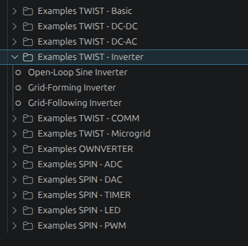
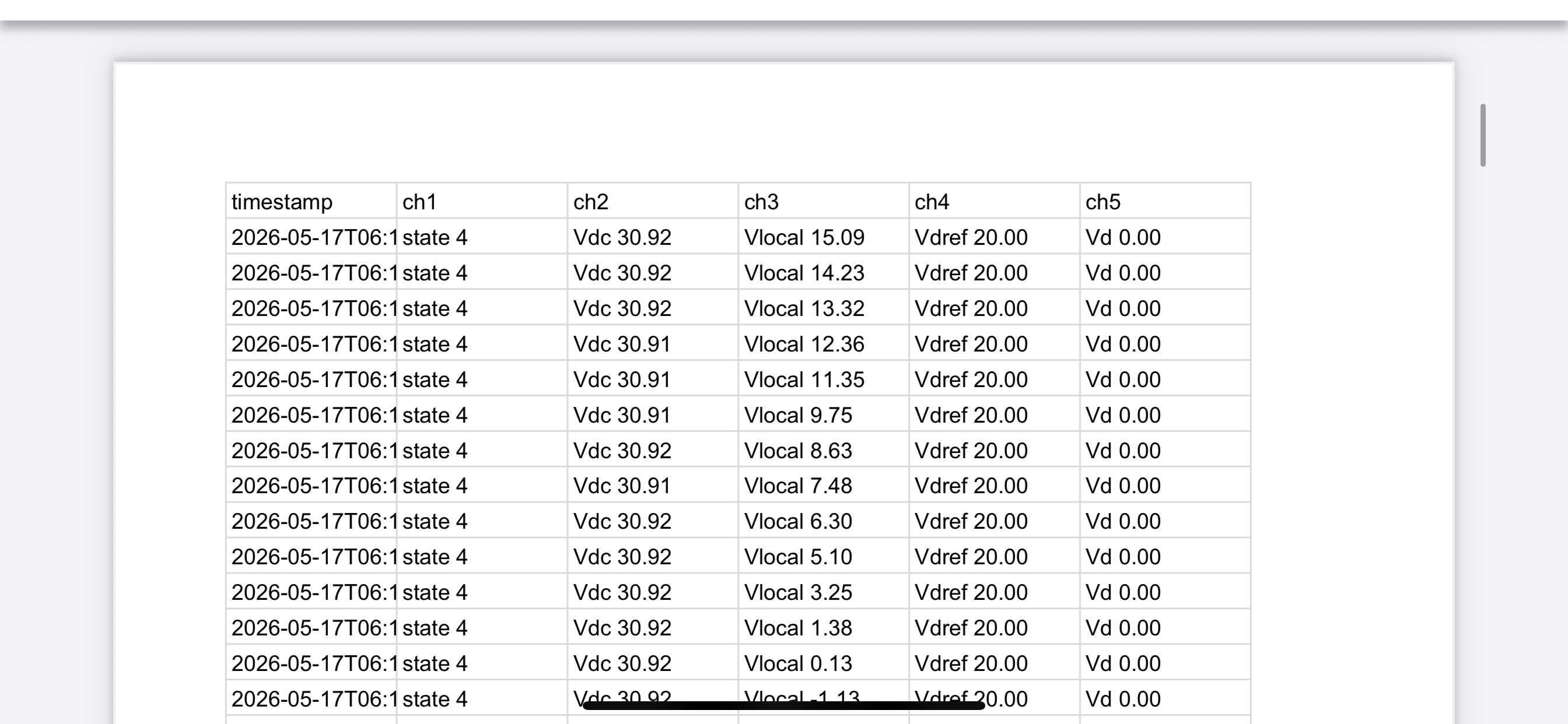
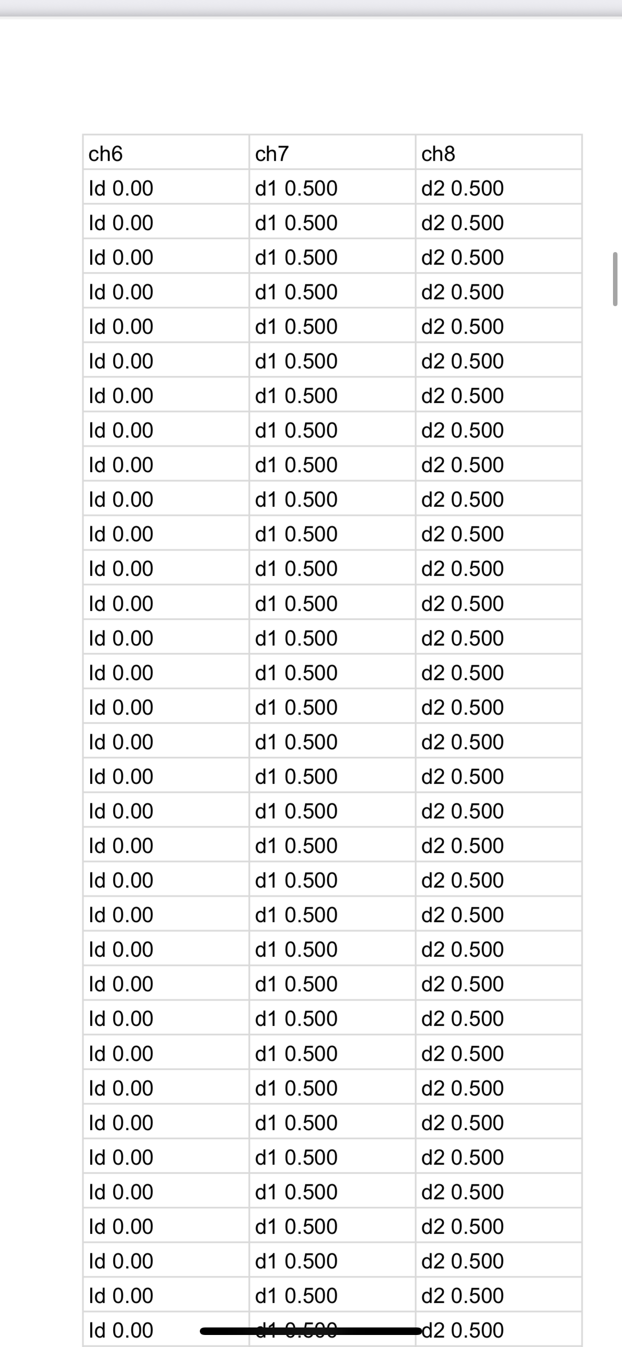
Another issue, which is interesting for your @LeqaaAwayssa :
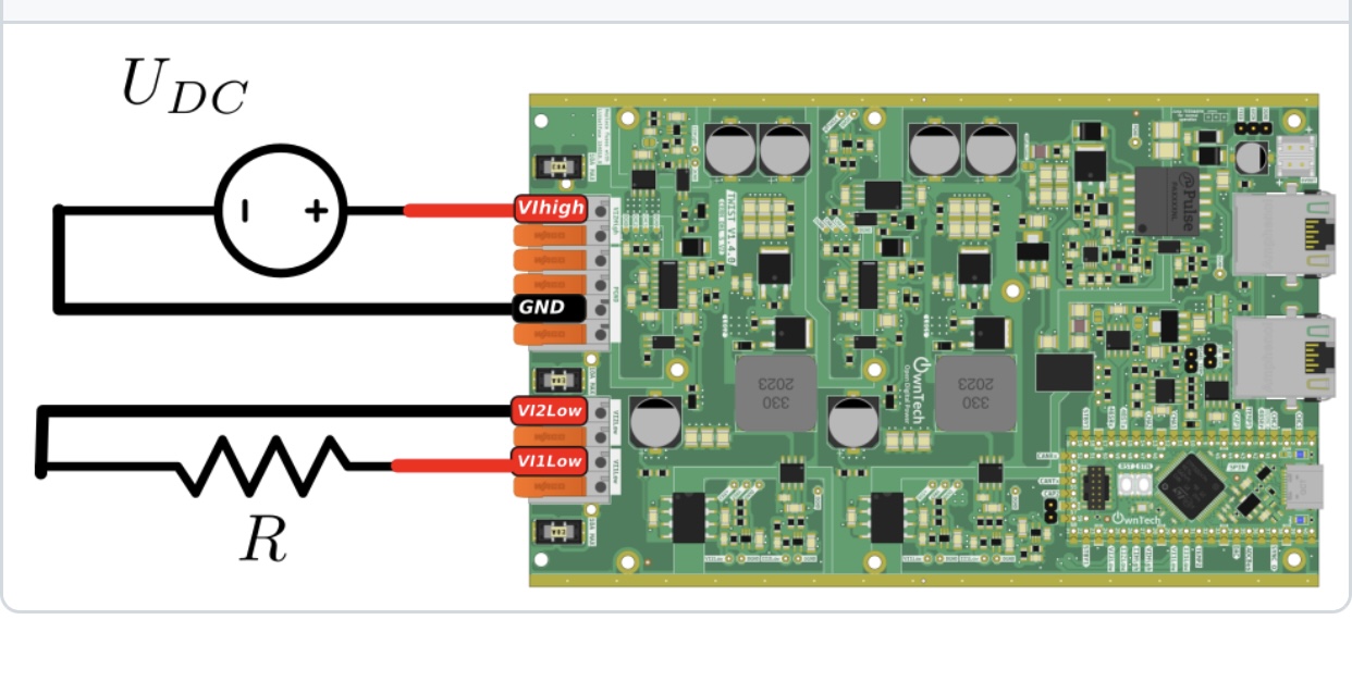
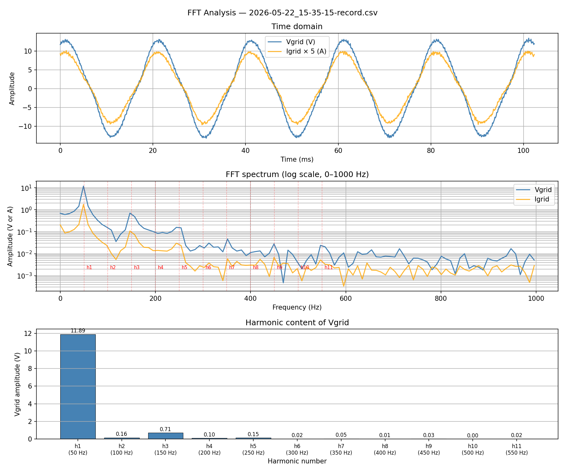
You should find the following result with a 10 \Omega resistor.
As you can see, there is a high level of 3rd harmonics in the system.
I got the following explanation for it:
Single-phase SOGI-DQ 2\omega resonance and 3rd harmonic injection
The problem
In a single-phase system, the SOGI-DQ transform cannot fully eliminate the fundamental
ripple from the DQ quantities the way a three-phase transform can. For an input signal
v(t) = A\cos(\omega t)
the ideal SOGI produces \alpha = A\cos(\omega t) and \beta = A\sin(\omega t), so the
Park transform gives a clean DC value V_d = A. In practice however, any amplitude or
phase imperfection in the SOGI output leaves a residual 2\omega (100 Hz) ripple on
V_d and I_d after the DQ transform:
V_d(t) = A + \varepsilon\cos(2\omega t) \qquad \text{(DC amplitude + 100 Hz ripple)}
How the 3rd harmonic is injected
The voltage outer-loop PI reacts to this 100 Hz ripple and drives a 100 Hz variation into
the DQ output voltage:
V_{d,\text{out}}(t) \approx A_\text{dc} + B\cos(2\omega t)
When this is converted back to the time domain via the inverse Park transform:
\begin{aligned}
V_\text{out}(t) &= V_{d,\text{out}}(t)\cdot\cos(\theta) \\
&= A_\text{dc}\cos(\omega t) + B\cos(2\omega t)\cos(\omega t) \\
&= A_\text{dc}\cos(\omega t) + \frac{B}{2}\cos(\omega t) + \frac{B}{2}\cos(3\omega t)
\end{aligned}
The product of the 2\omega ripple with the fundamental creates a 3rd harmonic at 150 Hz.
Measured result
The FFT of V_\text{grid} from the recording 2026-05-22_15-35-15-record.csv
(V_{d,\text{ref}} = 10\ \text{V}, V_\text{dc} \approx 30\ \text{V}, 10 kHz switching,
100 µs control period) confirms the mechanism:
| Harmonic |
Frequency |
V_\text{grid} amplitude |
THD contribution |
| h_1 |
50 Hz |
11.89 V |
— |
| h_3 |
150 Hz |
0.71 V |
5.95 % |
| h_5 |
250 Hz |
0.15 V |
1.26 % |
| h_2, h_4, \ldots |
even |
< 0.17\ \text{V} |
< 1.4\ \% |
| Total THD |
|
|
6.32 % |
The 3rd harmonic dominates, exactly matching the theoretical prediction.
![FFT analysis showing 3rd harmonic dominance]()
For now there is no fix. I suspect that by changing the phase shift this can be modified. Maybe you can verify?
Remember that you can use the t key to trigger and the r key to retrieve data via the scope mimicry.