Hello everyone, my name is Ziyad, and I am a third-year French student in Electrical Engineering and Industrial IT in Toulouse.
As part of my program, where M. VILLA Luis is our teacher, we will be using OwnTech equipment to successfully carry out the project assigned to us: creating a microgrid using different devices, as well as Twists to manage communication and perform certain measurements.
The project officially started yersterday as part of our academic program, under structured supervision.
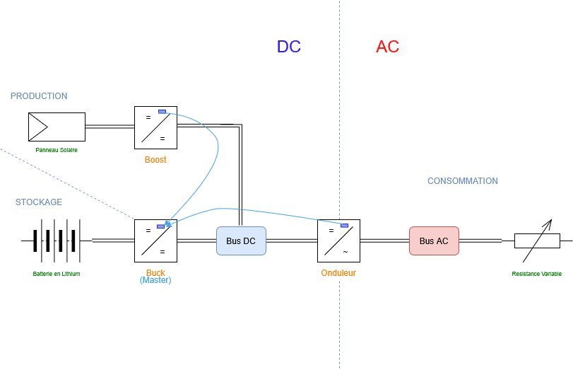
Production Team:
Boost converter to be tested. The solar panel voltage follows the reference voltage, but we do not yet know how much it increases the current. Session objective: build and run the test in order to determine the data to be transmitted.
Consumption Team:
Able to read the voltage; modulation is currently being implemented. Session objective: add the load (variable resistor), then take measurements (data to be transmitted).
Storage Team:
Buck converter operational. Voltage and current reading and recording implemented; beginning development of the program to control the rest of the system and read the state of charge (%). Session objective: test the lithium battery under real conditions to verify proper BMS operation.
#Inverter code (Twist) :/*
 * Copyright (c) 2021-present LAAS-CNRS
 *
 *   This program is free software: you can redistribute it and/or modify
 *   it under the terms of the GNU Lesser General Public License as published by
 *   the Free Software Foundation, either version 2.1 of the License, or
 *   (at your option) any later version.
 *
 *   This program is distributed in the hope that it will be useful,
 *   but WITHOUT ANY WARRANTY; without even the implied warranty of
 *   MERCHANTABILITY or FITNESS FOR A PARTICULAR PURPOSE.  See the
 *   GNU Lesser General Public License for more details.
 *
 *   You should have received a copy of the GNU Lesser General Public License
 *   along with this program.  If not, see <https://www.gnu.org/licenses/>.
 *
 * SPDX-License-Identifier: LGPL-2.1
 */

/**
 * @brief  This example demonstrates how to deploy a Buck converter with
 *         voltage mode control on the Twist power shield.
 *
 * @author Clément Foucher <[email protected]>
 * @author Luiz Villa <[email protected]>
 * @author Ayoub Farah Hassan <[email protected]>
 */

/*--------------Zephyr---------------------------------------- */
#include <zephyr/console/console.h>

/*--------------OWNTECH APIs---------------------------------- */
#include "ShieldAPI.h"
#include "SpinAPI.h"
#include "TaskAPI.h"

/*--------------OWNTECH Libraries----------------------------- */
#include "pid.h"

/*--------------SETUP FUNCTIONS DECLARATION------------------- */
/* Setups the hardware and software of the system */
void setup_routine();

/*--------------LOOP FUNCTIONS DECLARATION-------------------- */
/* Code to be executed in the slow communication task */
void loop_communication_task();
/* Code to be executed in the background task */
void loop_application_task();
/* Code to be executed in real time in the critical task */
void loop_critical_task();

/*--------------USER VARIABLES DECLARATIONS------------------- */

/* [us] period of the control task */
static uint32_t control_task_period = 100;
/* [bool] state of the PWM (ctrl task) */
static bool pwm_enable = false;

uint8_t received_serial_char;

/* Measure variables */

static float32_t V1_low_value;
static float32_t V2_low_value;
static float32_t I1_low_value;
static float32_t I2_low_value;
static float32_t I_high;
static float32_t V_high;

static float32_t temp_1_value;
static float32_t temp_2_value;

/* Temporary storage fore measured value (ctrl task) */
static float meas_data;

float32_t duty_cycle = 0.3;

/* Voltage reference */
static float32_t voltage_reference = 15;

/* PID coefficients for a 8.6ms step response*/
static float32_t kp = 0.000215;
static float32_t Ti = 7.5175e-5;
static float32_t Td = 0.0;
static float32_t N = 0.0;
static float32_t upper_bound = 1.0F;
static float32_t lower_bound = 0.0F;
static float32_t Ts = control_task_period * 1e-6;
static PidParams pid_params(Ts, kp, Ti, Td, N, lower_bound, upper_bound);
static Pid pid;

/*--------------------------------------------------------------- */

/* LIST OF POSSIBLE MODES FOR THE OWNTECH CONVERTER */
enum serial_interface_menu_mode { IDLEMODE = 0, POWERMODE };

uint8_t mode = IDLEMODE;

/*--------------SETUP FUNCTIONS------------------------------- */

/**
 * This is the setup routine.
 * Here the setup :
 *  - Initializes the power shield in Buck mode
 *  - Initializes the power shield sensors
 *  - Initializes the PID controller
 *  - Spawns three tasks.
 */
void setup_routine() {
  /* Buck voltage mode */
  shield.power.initBuck(ALL);

  shield.sensors.enableDefaultTwistSensors();

  pid.init(pid_params);

  /* Then declare tasks */
  uint32_t app_task_number = task.createBackground(loop_application_task);
  uint32_t com_task_number = task.createBackground(loop_communication_task);
  task.createCritical(loop_critical_task, 100);

  /* Finally, start tasks */
  task.startBackground(app_task_number);
  task.startBackground(com_task_number);
  task.startCritical();
}

/*--------------LOOP FUNCTIONS-------------------------------- */

/**
 * This tasks implements a minimalistic USB serial interface to control
 * the buck converter.
 */
void loop_communication_task() {
  received_serial_char = console_getchar();
  switch (received_serial_char) {
  case 'h':
    /*----------SERIAL INTERFACE MENU----------------------- */
    printk(" ________________________________________ \n"
           "|     ---- MENU buck voltage mode ----   |\n"
           "|     press i : idle mode                |\n"
           "|     press p : power mode               |\n"
           "|     press u : voltage reference UP     |\n"
           "|     press d : voltage reference DOWN   |\n"
           "|________________________________________|\n\n");
    /*------------------------------------------------------ */
    break;
  case 'i':
    printk("idle mode\n");
    mode = IDLEMODE;
    break;
  case 'p':
    printk("power mode\n");
    mode = POWERMODE;
    break;
  case 'u':
    voltage_reference += 0.5;
    break;
  case 'd':
    voltage_reference -= 0.5;
    break;
  default:
    break;
  }
}

/**
 * This is the code loop of the background task
 * This task mostly logs back measurements to the USB serial interface.
 */
void loop_application_task() {
  if (mode == IDLEMODE) {
    spin.led.turnOff();
  } else if (mode == POWERMODE) {
    spin.led.turnOn();

    shield.sensors.triggerTwistTempMeas(TEMP_SENSOR_1);
    shield.sensors.triggerTwistTempMeas(TEMP_SENSOR_2);

    meas_data = shield.sensors.getLatestValue(TEMP_SENSOR_1);
    if (meas_data != NO_VALUE)
      temp_1_value = meas_data;

    meas_data = shield.sensors.getLatestValue(TEMP_SENSOR_2);
    if (meas_data != NO_VALUE)
      temp_2_value = meas_data;

    // Affichage lisible avec etiquettes et unites (entiers car printk Zephyr ne
    // supporte pas %f)
    printk("V1=%d mV | V2=%d mV | V_HIGH=%d mV | I1=%d mA | I2=%d mA | "
           "I_HIGH=%d mA | Ref=%d mV | T1=%d mC | T2=%d mC\n",
           (int)(V1_low_value * 1000), (int)(V2_low_value * 1000),
           (int)(V_high * 1000), (int)(I1_low_value * 1000),
           (int)(I2_low_value * 1000), (int)(I_high * 1000),
           (int)(voltage_reference * 1000), (int)(temp_1_value * 1000),
           (int)(temp_2_value * 1000));
  }
  task.suspendBackgroundMs(100);
}

/**
 * This is the code loop of the critical task
 * This task runs at 10kHz.
 *  - It retrieves sensors values
 *  - It runs the PID controller
 *  - It update the PWM signals
 */
void loop_critical_task() {
  meas_data = shield.sensors.getLatestValue(I1_LOW);
  if (meas_data != NO_VALUE)
    I1_low_value = meas_data;

  meas_data = shield.sensors.getLatestValue(V1_LOW);
  if (meas_data != NO_VALUE)
    V1_low_value = meas_data;

  meas_data = shield.sensors.getLatestValue(V2_LOW);
  if (meas_data != NO_VALUE)
    V2_low_value = meas_data;

  meas_data = shield.sensors.getLatestValue(I2_LOW);
  if (meas_data != NO_VALUE)
    I2_low_value = meas_data;

  meas_data = shield.sensors.getLatestValue(I_HIGH);
  if (meas_data != NO_VALUE)
    I_high = meas_data;

  meas_data = shield.sensors.getLatestValue(V_HIGH);
  if (meas_data != NO_VALUE)
    V_high = meas_data;

  if (mode == IDLEMODE) {
    if (pwm_enable == true) {
      shield.power.stop(ALL);
    }
    pwm_enable = false;
  } else if (mode == POWERMODE) {
    duty_cycle = pid.calculateWithReturn(voltage_reference, V1_low_value);
    shield.power.setDutyCycle(ALL, duty_cycle);

    /* Set POWER ON */
    if (!pwm_enable) {
      pwm_enable = true;
      shield.power.start(ALL);
    }
  }
}

/**
 * This is the main function of this example
 * This function is generic and does not need editing.
 */
int main(void) {
  setup_routine();

  return 0;
}
#Buck code (Twist) : /*
 * Copyright (c) 2021-present LAAS-CNRS
 *
 *   This program is free software: you can redistribute it and/or modify
 *   it under the terms of the GNU Lesser General Public License as published by
 *   the Free Software Foundation, either version 2.1 of the License, or
 *   (at your option) any later version.
 *
 *   This program is distributed in the hope that it will be useful,
 *   but WITHOUT ANY WARRANTY; without even the implied warranty of
 *   MERCHANTABILITY or FITNESS FOR A PARTICULAR PURPOSE.  See the
 *   GNU Lesser General Public License for more details.
 *
 *   You should have received a copy of the GNU Lesser General Public License
 *   along with this program.  If not, see <https://www.gnu.org/licenses/>.
 *
 * SPDX-License-Identifier: LGPL-2.1
 */

/**
 * @brief  This example demonstrates how to deploy a Buck converter with
 *         voltage mode control on the Twist power shield.
 *
 * @author Clément Foucher <[email protected]>
 * @author Luiz Villa <[email protected]>
 * @author Ayoub Farah Hassan <[email protected]>
 */

/*--------------Zephyr---------------------------------------- */
#include <zephyr/console/console.h>

/*--------------OWNTECH APIs---------------------------------- */
#include "ShieldAPI.h"
#include "SpinAPI.h"
#include "TaskAPI.h"

/*--------------OWNTECH Libraries----------------------------- */
#include "pid.h"

/*--------------SETUP FUNCTIONS DECLARATION------------------- */
/* Setups the hardware and software of the system */
void setup_routine();

/*--------------LOOP FUNCTIONS DECLARATION-------------------- */
/* Code to be executed in the slow communication task */
void loop_communication_task();
/* Code to be executed in the background task */
void loop_application_task();
/* Code to be executed in real time in the critical task */
void loop_critical_task();

/*--------------USER VARIABLES DECLARATIONS------------------- */

/* [us] period of the control task */
static uint32_t control_task_period = 100;
/* [bool] state of the PWM (ctrl task) */
static bool pwm_enable = false;

uint8_t received_serial_char;

/* Measure variables */

static float32_t V1_low_value;
static float32_t V2_low_value;
static float32_t I1_low_value;
static float32_t I2_low_value;
static float32_t I_high;
static float32_t V_high;

static float32_t temp_1_value;
static float32_t temp_2_value;

/* Temporary storage fore measured value (ctrl task) */
static float meas_data;

float32_t duty_cycle = 0.3;

/* Voltage reference */
static float32_t voltage_reference = 15;

/* PID coefficients for a 8.6ms step response*/
static float32_t kp = 0.000215;
static float32_t Ti = 7.5175e-5;
static float32_t Td = 0.0;
static float32_t N = 0.0;
static float32_t upper_bound = 1.0F;
static float32_t lower_bound = 0.0F;
static float32_t Ts = control_task_period * 1e-6;
static PidParams pid_params(Ts, kp, Ti, Td, N, lower_bound, upper_bound);
static Pid pid;

/*--------------------------------------------------------------- */

/* LIST OF POSSIBLE MODES FOR THE OWNTECH CONVERTER */
enum serial_interface_menu_mode { IDLEMODE = 0, POWERMODE };

uint8_t mode = IDLEMODE;

/*--------------SETUP FUNCTIONS------------------------------- */

/**
 * This is the setup routine.
 * Here the setup :
 *  - Initializes the power shield in Buck mode
 *  - Initializes the power shield sensors
 *  - Initializes the PID controller
 *  - Spawns three tasks.
 */
void setup_routine() {
  /* Buck voltage mode */
  shield.power.initBuck(ALL);

  shield.sensors.enableDefaultTwistSensors();

  pid.init(pid_params);

  /* Then declare tasks */
  uint32_t app_task_number = task.createBackground(loop_application_task);
  uint32_t com_task_number = task.createBackground(loop_communication_task);
  task.createCritical(loop_critical_task, 100);

  /* Finally, start tasks */
  task.startBackground(app_task_number);
  task.startBackground(com_task_number);
  task.startCritical();
}

/*--------------LOOP FUNCTIONS-------------------------------- */

/**
 * This tasks implements a minimalistic USB serial interface to control
 * the buck converter.
 */
void loop_communication_task() {
  received_serial_char = console_getchar();
  switch (received_serial_char) {
  case 'h':
    /*----------SERIAL INTERFACE MENU----------------------- */
    printk(" ________________________________________ \n"
           "|     ---- MENU buck voltage mode ----   |\n"
           "|     press i : idle mode                |\n"
           "|     press p : power mode               |\n"
           "|     press u : voltage reference UP     |\n"
           "|     press d : voltage reference DOWN   |\n"
           "|________________________________________|\n\n");
    /*------------------------------------------------------ */
    break;
  case 'i':
    printk("idle mode\n");
    mode = IDLEMODE;
    break;
  case 'p':
    printk("power mode\n");
    mode = POWERMODE;
    break;
  case 'u':
    voltage_reference += 0.5;
    break;
  case 'd':
    voltage_reference -= 0.5;
    break;
  default:
    break;
  }
}

/**
 * This is the code loop of the background task
 * This task mostly logs back measurements to the USB serial interface.
 */
void loop_application_task() {
  if (mode == IDLEMODE) {
    spin.led.turnOff();
  } else if (mode == POWERMODE) {
    spin.led.turnOn();

    shield.sensors.triggerTwistTempMeas(TEMP_SENSOR_1);
    shield.sensors.triggerTwistTempMeas(TEMP_SENSOR_2);

    meas_data = shield.sensors.getLatestValue(TEMP_SENSOR_1);
    if (meas_data != NO_VALUE)
      temp_1_value = meas_data;

    meas_data = shield.sensors.getLatestValue(TEMP_SENSOR_2);
    if (meas_data != NO_VALUE)
      temp_2_value = meas_data;

    // Affichage lisible avec etiquettes et unites (entiers car printk Zephyr ne
    // supporte pas %f)
    printk("V1=%d mV | V2=%d mV | V_HIGH=%d mV | I1=%d mA | I2=%d mA | "
           "I_HIGH=%d mA | Ref=%d mV | T1=%d mC | T2=%d mC\n",
           (int)(V1_low_value * 1000), (int)(V2_low_value * 1000),
           (int)(V_high * 1000), (int)(I1_low_value * 1000),
           (int)(I2_low_value * 1000), (int)(I_high * 1000),
           (int)(voltage_reference * 1000), (int)(temp_1_value * 1000),
           (int)(temp_2_value * 1000));
  }
  task.suspendBackgroundMs(100);
}

/**
 * This is the code loop of the critical task
 * This task runs at 10kHz.
 *  - It retrieves sensors values
 *  - It runs the PID controller
 *  - It update the PWM signals
 */
void loop_critical_task() {
  meas_data = shield.sensors.getLatestValue(I1_LOW);
  if (meas_data != NO_VALUE)
    I1_low_value = meas_data;

  meas_data = shield.sensors.getLatestValue(V1_LOW);
  if (meas_data != NO_VALUE)
    V1_low_value = meas_data;

  meas_data = shield.sensors.getLatestValue(V2_LOW);
  if (meas_data != NO_VALUE)
    V2_low_value = meas_data;

  meas_data = shield.sensors.getLatestValue(I2_LOW);
  if (meas_data != NO_VALUE)
    I2_low_value = meas_data;

  meas_data = shield.sensors.getLatestValue(I_HIGH);
  if (meas_data != NO_VALUE)
    I_high = meas_data;

  meas_data = shield.sensors.getLatestValue(V_HIGH);
  if (meas_data != NO_VALUE)
    V_high = meas_data;

  if (mode == IDLEMODE) {
    if (pwm_enable == true) {
      shield.power.stop(ALL);
    }
    pwm_enable = false;
  } else if (mode == POWERMODE) {
    duty_cycle = pid.calculateWithReturn(voltage_reference, V1_low_value);
    shield.power.setDutyCycle(ALL, duty_cycle);

    /* Set POWER ON */
    if (!pwm_enable) {
      pwm_enable = true;
      shield.power.start(ALL);
    }
  }
}

/**
 * This is the main function of this example
 * This function is generic and does not need editing.
 */
int main(void) {
  setup_routine();

  return 0;
}
#Boost code (Twist) : /*
 * Copyright (c) 2021-present LAAS-CNRS
 *
 *   This program is free software: you can redistribute it and/or modify
 *   it under the terms of the GNU Lesser General Public License as published by
 *   the Free Software Foundation, either version 2.1 of the License, or
 *   (at your option) any later version.
 *
 *   This program is distributed in the hope that it will be useful,
 *   but WITHOUT ANY WARRANTY; without even the implied warranty of
 *   MERCHANTABILITY or FITNESS FOR A PARTICULAR PURPOSE.  See the
 *   GNU Lesser General Public License for more details.
 *
 *   You should have received a copy of the GNU Lesser General Public License
 *   along with this program.  If not, see <https://www.gnu.org/licenses/>.
 *
 * SPDX-License-Identifier: LGPL-2.1
 */

/**
 * @brief  This example shows how to implement a closed loop voltage mode
 *         boost converter with a Twist power shield.
 *
 * @author Clément Foucher <[email protected]>
 * @author Luiz Villa <[email protected]>
 * @author Ayoub Farah Hassan <[email protected]>
 */

/*--------------Zephyr---------------------------------------- */
#include <zephyr/console/console.h>

/*--------------OWNTECH APIs---------------------------------- */
#include "SpinAPI.h"
#include "ShieldAPI.h"
#include "TaskAPI.h"
#include "CommunicationAPI.h"

/*--------------OWNTECH Libraries----------------------------- */
#include "pid.h"

/*--------------SETUP FUNCTIONS DECLARATION------------------- */
/* Setups the hardware and software of the system */
void setup_routine();

/*--------------LOOP FUNCTIONS DECLARATION-------------------- */
/* Code to be executed in the slow communication task */
void loop_communication_task();
/* Code to be executed in the background task */
void loop_application_task();
/* Code to be executed in real time in the critical task */
void loop_critical_task();

/*--------------USER VARIABLES DECLARATIONS------------------- */

/* [us] period of the control task */
static uint32_t control_task_period = 100;
/* [bool] state of the PWM (ctrl task) */
static bool pwm_enable = false;

uint8_t received_serial_char;

/* Measure variables */
static float32_t V1_low_value;
static float32_t V2_low_value;
static float32_t I1_low_value;
static float32_t I2_low_value;
/* Valeurs côté haute tension */
static float32_t I_high;
static float32_t V_high;
static float32_t P_high;

/* Temporary storage for measured value (ctrl task) */
static float meas_data;

float32_t duty_cycle = 0.3;

/* Voltage reference */
static float32_t voltage_reference = 33;

/* Maximum Voltage */
static float32_t VMAX = 40;

/* Duty Cycle Max */
static float32_t duty_max=0.66;

/* PID coefficient for a 8.6ms step response*/
static float32_t kp = 0.000215;
static float32_t Ti = 7.5175e-5;
static float32_t Td = 0.0;
static float32_t N = 0.0;
static float32_t upper_bound = 1.0F;
static float32_t lower_bound = 0.0F;
static float32_t Ts = control_task_period * 1.e-6F;
static PidParams pid_params(Ts, kp, Ti, Td, N, lower_bound, upper_bound);
static Pid pid;
/* Variables pour le calcul de moyenne */
static float32_t somme_P;
static float32_t somme_V;
/* Variables pour le calcul des variations */
static float32_t dP;
static float32_t dV;
/* Pas de variation de tension */
float32_t voltage_step = 0.1;

/* Valeurs précédentes pour les calculs */
static float32_t V_high_prec = 0;
static float32_t P_high_prec = 0;
/* Compteurs et temporisation */
int i = 0;
int f = 0;
int time = 0;
int h = 0;

/*--------------------------------------------------------------- */

/* LIST OF POSSIBLE MODES FOR THE OWNTECH CONVERTER */
enum serial_interface_menu_mode
{
    IDLEMODE = 0,
    POWERMODE
};

uint8_t mode = IDLEMODE;

/*--------------SETUP FUNCTIONS------------------------------- */

/**
 * This is the setup routine.
 * Here the setup :
 *  - Initializes the power shield in Boost mode
 *  - Initializes the power shield sensors
 *  - Initializes the PID controller
 *  - Spawns three tasks.
 */
void setup_routine()
{
    /* Boost voltage mode */
    shield.power.initBoost(ALL);

    shield.sensors.enableDefaultTwistSensors();

    pid.init(pid_params);

    /* Then declare tasks */
    uint32_t app_task_number = task.createBackground(loop_application_task);
    uint32_t com_task_number = task.createBackground(loop_communication_task);
    task.createCritical(loop_critical_task, 100);


    /* Finally, start tasks */
    task.startBackground(app_task_number);
    task.startBackground(com_task_number);
    task.startCritical();
}

/*--------------LOOP FUNCTIONS-------------------------------- */

/**
 * This tasks implements a minimalistic USB serial interface to control
 * the boost converter.
 */
void loop_communication_task()
{
    received_serial_char = console_getchar();
    switch (received_serial_char)
    {
    case 'h':
        /*----------SERIAL INTERFACE MENU----------------------- */
        printk(" ________________________________________ \n"
               "|     --- MENU boost voltage mode ---    |\n"
               "|     press i : idle mode                |\n"
               "|     press p : power mode               |\n"
               "|     press u : voltage reference UP     |\n"
               "|     press d : voltage reference DOWN   |\n"
               "|________________________________________|\n\n");
        /*------------------------------------------------------ */
        break;
    case 'i':
        printk("idle mode\n");
        mode = IDLEMODE;
        break;
    case 'p':
        printk("power mode\n");
        mode = POWERMODE;
 f = 0;
        time = 0;
        h = 0;
        break;
    case 'u':
        voltage_reference += 0.5;
        break;
    case 'd':
        voltage_reference -= 0.5;
        break;
    default:
        break;
    }
}

/**
 * This is the code loop of the background task
 * This task mostly logs back measurements to the USB serial interface.
 */
void loop_application_task()
{
    if (mode == IDLEMODE)
    {
        spin.led.turnOff();
    }
    else if (mode == POWERMODE)
    {
        // Allume la LED pour indiquer le mode POWER
        spin.led.turnOn();


        /* Algorithme de recherche du point de puissance maximale */
        /* Phase initiale: Balayage de la tension de référence */
        if (f == 0)
        {
            // Diminue progressivement la tension de référence jusqu'à 10V pour tracer la courbe I*V
            if (voltage_reference >= 10)
                voltage_reference -= 0.5;
            else
            {
                f += 1;
                printk("Courbe I*V fin\n");
            }
        }
        /* Phase MPPT: Recherche du point de puissance maximale */
        else
        {
            h++;
            i++;
            // Affiche l'en-tête des données au premier passage
            if (h == 1)
            {
                voltage_reference = 30;
                printk("I1_low_value");
                printk(":V1_low_value");
                printk(":voltage_reference");
                printk(":I2_low_value");
                printk(":V2_low_value");
                printk(":P_high_prec");
                printk(":I_high");
                printk(":V_high");
                printk(":duty_cycle");
                printk(":time");
                printk("\n");
            }

            /* Calcul de la puissance instantanée et moyennes glissantes */
            P_high = V_high * I_high;
            somme_P += P_high;
            somme_V += V_high;

            // Calcule les moyennes sur 6 échantillons
            if (i == 6)
            {
                P_high = somme_P / 6;
                somme_V = somme_V / 6;

                /* Algorithme MPPT (Maximum Power Point Tracking) */
                // Calcul des variations de puissance et tension
                dP = P_high - P_high_prec;
                dV = somme_V - V_high_prec;

                // Ajuste la tension de référence selon l'algorithme P&O (Perturb & Observe)
                if (dP > 0)
                    if (dV > 0)
                        voltage_reference -= voltage_step;
                    else
                        voltage_reference += voltage_step;
                else if (dV < 0)
                    voltage_reference -= voltage_step;
                else
                    voltage_reference += voltage_step;

                // Réinitialise les compteurs et sauvegarde les valeurs précédentes
                i = 0;
                P_high_prec = P_high;
                V_high_prec = somme_V;
                somme_P = 0;
                somme_V = 0;

                // Passe en mode IDLE si la puissance devient négative
                if (P_high < 0)
                {
                    mode = IDLEMODE;
                }
            }
        }
    }

    /* Affichage des mesures sur le port série */
    // Affiche toutes les mesures avec 3 décimales
    printk("%.3f:", (double)I1_low_value);
    printk("%.3f:", (double)V1_low_value);
    printk("%.3f:", (double)voltage_reference);
    printk("%.3f:", (double)I2_low_value);
    printk("%.3f:", (double)V2_low_value);
    printk("%.3f:", (double)P_high);
    printk("%.3f:", (double)I_high);
    printk("%.3f:", (double)V_high);
    duty_cycle = pid.calculateWithReturn(voltage_reference, V_high);
    printk("%.3f:", (double)duty_cycle);
    printk("%.3f:", (double)time);
    printk("\n");

    // Incrémente le temps et met en pause la tâche pendant 100ms
    time += 100;
    task.suspendBackgroundMs(100);
}

/**
 * This is the code loop of the critical task
 * This task runs at 10kHz.
 *  - It retrieves sensor values
 *  - It runs the PID controller
 *  - It update the PWM signals
 */
void loop_critical_task()
{
    meas_data = shield.sensors.getLatestValue(I1_LOW);
    if (meas_data != NO_VALUE) I1_low_value = meas_data;

    meas_data = shield.sensors.getLatestValue(V1_LOW);
    if (meas_data != NO_VALUE) V1_low_value = meas_data;

    meas_data = shield.sensors.getLatestValue(I_HIGH);
    if (meas_data != NO_VALUE) I_high = meas_data;

    meas_data = shield.sensors.getLatestValue(V_HIGH);
    if (meas_data != NO_VALUE) V_high = meas_data;

    if(V_high>VMAX) mode = IDLEMODE;

    if (mode == IDLEMODE)
    {
        if (pwm_enable == true)
        {
            shield.power.stop(LEG1);
        }
        pwm_enable = false;
    }
    else if (mode == POWERMODE)
    {
        duty_cycle = pid.calculateWithReturn(voltage_reference, V1_low_value);
        if((1-duty_cycle) < duty_max) shield.power.setDutyCycle(LEG1,1-duty_cycle);
        else
        {
            shield.power.stop(LEG1);
            pwm_enable = false;
            printk("Idle auto\n");
        }

        /* Set POWER ON */
        if (!pwm_enable)
        {
            pwm_enable = true;
            shield.power.start(LEG1);
        }
    }

}

/**
 * This is the main function of this example
 * This function is generic and does not need editing.
 */
int main(void)
{
    setup_routine();

    return 0;
}