Help with configuring OwnTech Ownverter 1.1.0 for driving OZO 36V AC moto

Hello everyone, we are GEII students at the IUT of Lille. We are working on a project where, starting from a DC power source, we need to supply an OZO 36 V AC motor. For this, we are using the OwnTech Ownverter 1.1.0 board to generate the AC output.

We are writing here because, after studying the documentation and searching online, we are having difficulties understanding how to properly configure the board. We have two questions:

  1. We are currently using the example program “FOC with HALL sensor” to generate the AC output.
    Is this example appropriate for our project, and can it be used without modification, or do we need to write our own program?

  2. With this example program, we applied 12 V DC to the input and measured the three output phases (with no load connected). On the oscilloscope, we observed that two of the phases were superimposed (in phase), while the third was in opposition.
    We wanted to test the system without a load, and we assumed this behavior was because we had not connected the Hall effect sensors.
    Is this indeed the reason for the issue? And if we connect the motor with its Hall sensors, will the phase problem be resolved?

Thank you in advance, and have a nice day everyone.

PS : Here is a photo of the program and the wiring we used. (A+, B+, and C+

are connected to the oscilloscope.)

Hello @GEII_IUT_LILLE_Delh ,

Thank you for your message. Sorry for the time to reply.

Can you please put your main.cpp here? This way I can reproduce what you are doing.

And also, can you please upload a schematic of your connexion? You can use the ones available here

The image of the board and the circuit in figure 17 are editable.

If you click on the image of the board and then the pencil button as below you will open a draw.io link

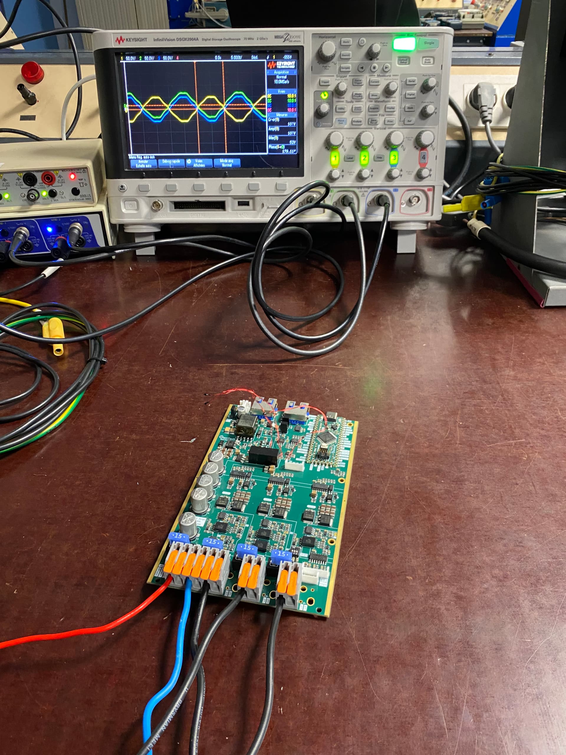
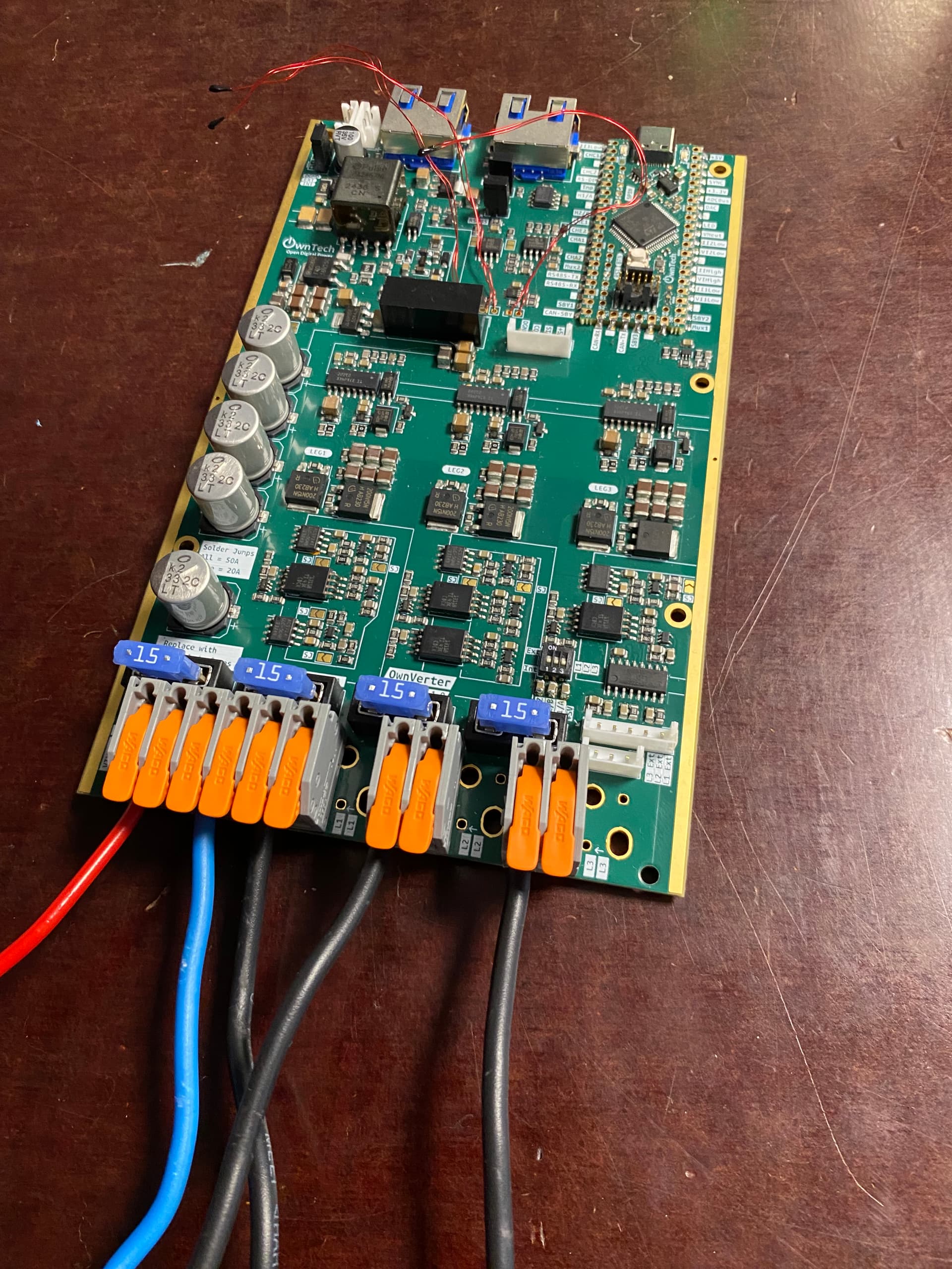
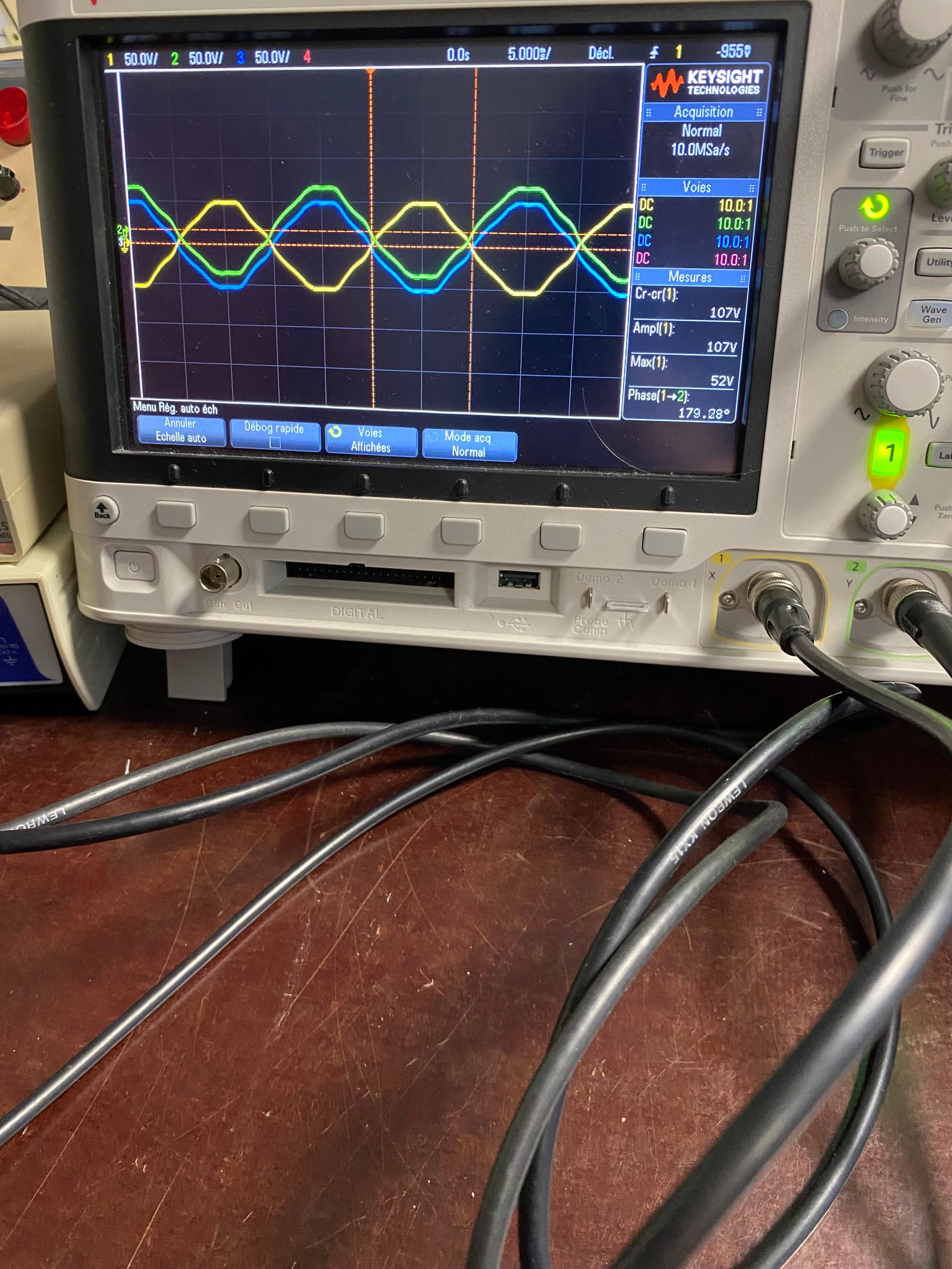
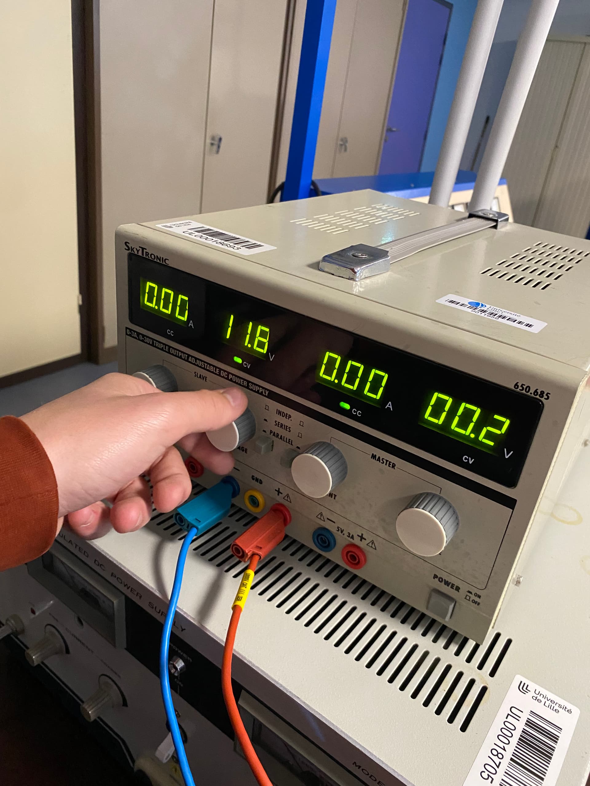
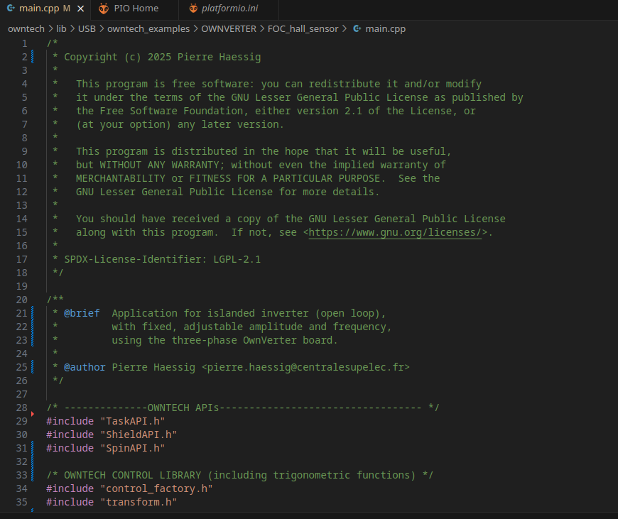
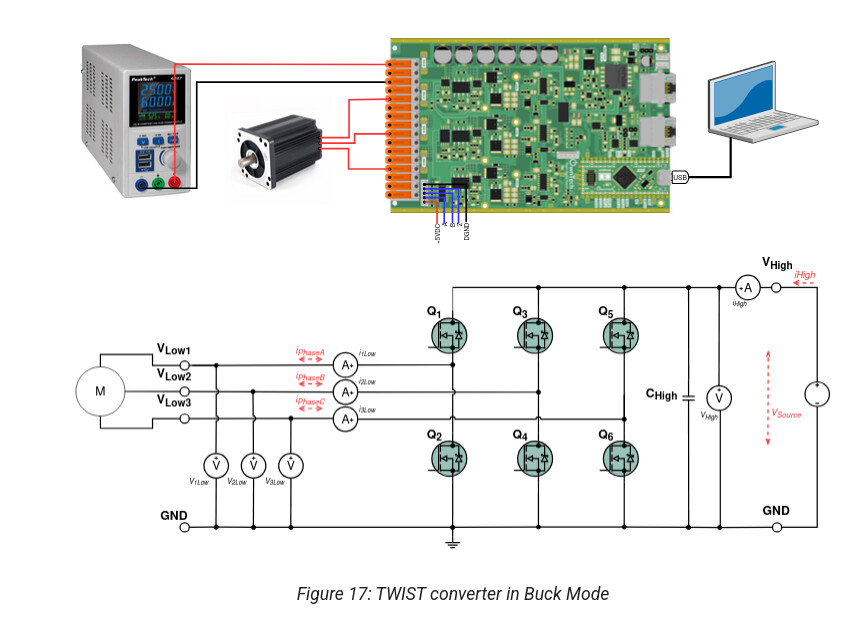
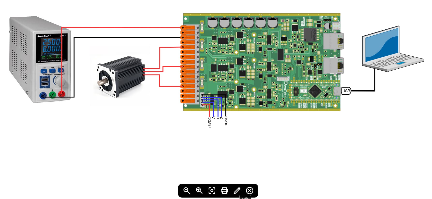
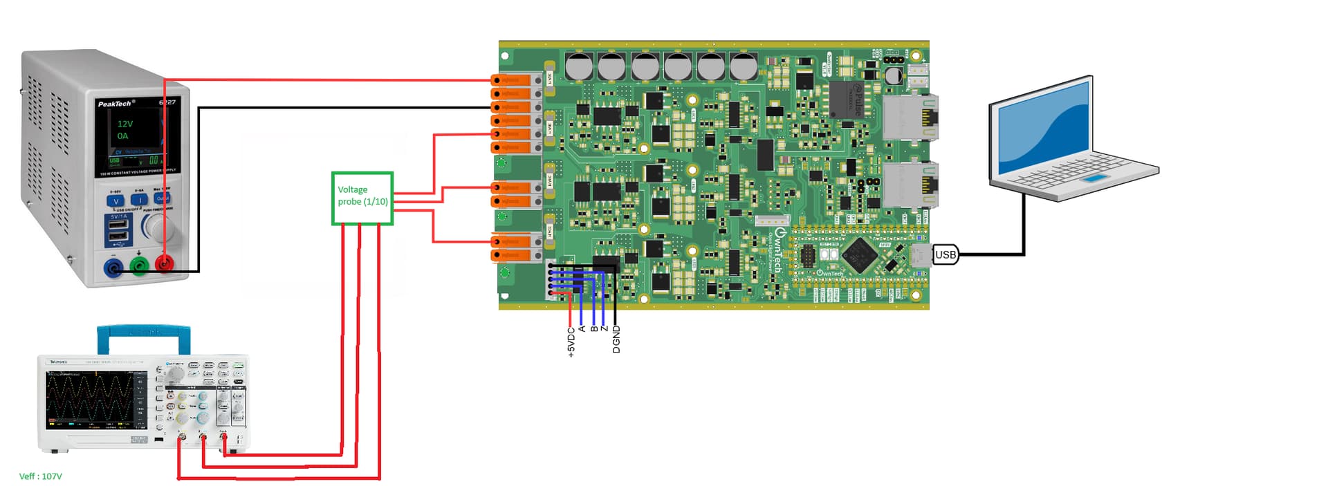
Hello ! Thank you for your response. Here’s our scematic connexion and our main.cpp

And the main.cpp :


/\*

* Copyright (c) 2024-present LAAS-CNRS
* 
* This program is free software: you can redistribute it and/or modify
* it under the terms of the GNU Lesser General Public License as published by
* the Free Software Foundation, either version 2.1 of the License, or
* (at your option) any later version.
* 
* This program is distributed in the hope that it will be useful,
* but WITHOUT ANY WARRANTY; without even the implied warranty of
* MERCHANTABILITY or FITNESS FOR A PARTICULAR PURPOSE.  See the
* GNU Lesser General Public License for more details.
* 
* You should have received a copy of the GNU Lesser General Public License
* along with this program.  If not, see <https://www.gnu.org/licenses/>.
* 
* SPDX-License-Identifier: LGPL-2.1
  \*/

/\*\*

* @briefbrief  This file is an example of a Field Oriented Control for
* 
      OwnTech OwnVerter board.
  
* 
      Please check example documentation to get more details
  
* 
      how to use this example: https://docs.owntech.org/examples/
  
* @author
* @author Régis Ruelland <regis.ruelland@>@author<aas.fr>
* @author Jean Alinei <[email protected]>
  \*/

/\* --------------OWNTECH APIs---------------------------------- \*/

#include “ScopeMimicry.h”
#include “SpinAPI.h”
#include “TaskAPI.h”
#include “ShieldAPI.h”
#include “arm_math_types.h”
#include “control_factory.h”
#include “transform.h”
#include “trigo.h”
#include “zephyr/console/console.h”

/\* --------------SETUP FUNCTIONS DECLARATION------------------- \*/

/\* Setups the hardware and software of the system \*/
void setup_routine();

/\* --------------LOOP FUNCTIONS DECLARATION-------------------- \*/

/\* Code to be executed in the background task */
void loop_background_task();
/* Code to be executed in real time in the critical \*/
void loop_critical_task();
void application_task();

/\* --------------USER VARIABLES DECLARATIONS------------------- \*/
#define HALL1 PC6
#define HALL2 PC7
#define HALL3 PD2

static const float32_t AC_CURRENT_LIMIT = 3.0;
static const float32_t DC_CURRENT_LIMIT = 2.0;

/\* Used in the control algorithm */
static const float32_t MIN_DC_VOLTAGE = 30.0F;
/* Used as a threshold to start POWER mode \*/
static const float32_t V_HIGH_MIN = 5.0;
static const float32_t Ts = 100.e-6F;
static const uint32_t control_task_period = (uint32_t)(Ts \* 1.e6F);

/\* Hall effect sensors \*/
static uint8_t HALL1_value;
static uint8_t HALL2_value;
static uint8_t HALL3_value;

static uint8_t angle_index;
static float32_t hall_angle;
static PllAngle pllangle = controlLibFactory.pllAngle(Ts, 10.0F, 0.04F);
static PllDatas pllDatas;
static float32_t angle_filtered;
static float32_t w_meas;

/\*

* One sector for one index value
* Index = H1*2^0 + H2*2^1 + H3\*2^2
  \*/
  static int16_t sector[ ] = {-1, 5, 1, 0, 3, 4, 2};
  static float32_t k_angle_offset = 0.0F;

/\* Power LEG measures \*/
static float32_t meas_data;
static float32_t I1_low_value;
static float32_t I2_low_value;
static float32_t I1_offset;
static float32_t I2_offset;
static float32_t tmpI1_offset;
static float32_t tmpI2_offset;
static const float32_t NB_OFFSET = 2000.0;
static float32_t V1_low_value;
static float32_t V2_low_value;
static float32_t V12_value;

/\* DC measures \*/
static float32_t I_high;
static float32_t V_high;

/\* Three phase system and Park DQ Frame (dqo) \*/
static three_phase_t Vabc;
static three_phase_t duty_abc;
static three_phase_t Iabc;
static dqo_t Vdq;
static dqo_t Idq;
static dqo_t Idq_ref;
static float32_t angle_4_control;

/\* Variables used to get static value for ScopeMimicry \*/
static three_phase_t Iabc_ref;
static float32_t duty_a, duty_b;
static float32_t Ia_ref;
static float32_t Ib_ref;
static float32_t Va;
static float32_t Iq_meas;
static float32_t Iq_ref;
static float32_t Iq_max;
static float32_t Vd, Vq;
static float32_t HALL1_value_f;
static float32_t HALL2_value_f;
static float32_t HALL3_value_f;
static float32_t angle_index_f;

/\* We only make torque control. \*/
static float32_t manual_Iq_ref;

/\*\*

* Low Pass Filters Init
  \*/
  static LowPassFirstOrderFilter vHigh_filter =
  controlLibFactory.lowpassfilter(Ts, 5.0e-3F);

static LowPassFirstOrderFilter w_mes_filter =
controlLibFactory.lowpassfilter(Ts, 5.0e-3F);

static float32_t V_high_filtered;
static float32_t inverse_Vhigh;

/\*\*

* PID
  \*/

static float32_t Kp = 30 \* 0.035;
static float32_t Ti = 0.002029;
static float32_t Td = 0.0F;
static float32_t N = 1.0;
/\* Coefficient 0.4 comes from Va_max =  (α\_max - 0.5) \* Udc     \*/
static float32_t lower_bound = -MIN_DC_VOLTAGE \* 0.4;
static float32_t upper_bound = MIN_DC_VOLTAGE \* 0.4;
static Pid pi_d = controlLibFactory.pid(Ts, Kp, Ti, Td, N,
lower_bound, upper_bound);

static Pid pi_q = controlLibFactory.pid(Ts, Kp, Ti, Td, N,
lower_bound, upper_bound);

/\* Decimation is used to limit the rate of measurement plotted in ScopeMimicry\*/
const static uint32_t decimation = 10;
static uint32_t counter_time;
float32_t counter_time_f;
static float32_t w_estimate;
uint8_t received_serial_char;

/\* List of possible modes for the OwnTech power shield \*/
enum serial_interface_menu_mode
{
IDLEMODE = 0,
POWERMODE = 1,
};

/\* List of possible control states \*/
enum control_state_mode {
OFFSET_ST = 0,
IDLE_ST = 1,
POWER_ST = 2,
ERROR_ST = 3
};

enum control_state_mode control_state;
static float32_t control_state_f;

static uint16_t error_counter;
static bool pwm_enable;
uint8_t asked_mode = IDLEMODE;

/\*\*

* Definition of variables and functions for plotting real time values
* using ScopeMimicry.
  \*/

const uint16_t SCOPE_SIZE = 512;
uint16_t k_app_idx;
ScopeMimicry scope(SCOPE_SIZE, 12);
static bool is_downloading;
static bool memory_print;

bool mytrigger()
{
return (control_state == POWER_ST);
}

void dump_scope_datas(ScopeMimicry &scope) {
printk(“begin record\\n”);
scope.reset_dump();
while (scope.get_dump_state() != finished) {
printk(“%s”, scope.dump_datas());
task.suspendBackgroundUs(200);
}
printk(“end record\\n”);
}

/\*\*

* VHigh Filter and PID init function
  \*/
  void init_filt_and_reg(void)
  {
  pllangle.reset(0.F)@brief
  vHigh_filt@[email protected](V_HIGH_MIN);
  pi_d.reset();
  pi_q.reset();
  error_counter = 0;
  }

/\*\*

* @brief A period-meter function which estim@paramte pu@paramsation
* @paramor the sector varia@paramle (one integer@@returnaramvalue@paramcorrespond@retur@returnto π/3).
* 
* @param sector assume sector is integer in \[0, 5\]
* @param time in \[s\]
* @return pulsation (float)
  */
  float32_t pulsation_estimator(int16_t sector, float32_t time)
  {
  static float32_t w_estimate_intern = 0.0F;
  static int16_t prev_sector;
  static float32_t prev_time = 0.0F;
  int16_t delta_sector;
  float32_t sixty_degre_step_time;
  delta_sector = sector - prev_sector;
  prev_sector = sector;
  if (delta_sector == 1 || delta_sector == -5) {
  /* positive speed \*/
  sixty_degre_step_time = (time - prev_time);
  w_estimate_intern = (PI / 3.0) / sixty_degre_step_time;
  prev_time = time;
  }
  if (delta_sector == -1 || delta_sector == 5) {
  sixty_degre_step_time = (time - prev_time);
  w_estimate_intern = (-PI / 3.0) / sixty_degre_step_time;
  prev_time = time;
  }
  return w_estimate_intern;
  }

/\*\*

* Function that retrieves necessary measurements from power shield sensors.
  \*/
  inline void retrieve_analog_datas()
  {
  meas_data = shield.sensors.getLatestValue(I1_LOW);
  if (meas_data != NO_VALUE) {
  I1_low_value = meas_data + I1_offset;
  }

  meas_data = shield.sensors.getLatestValue(I2_LOW);
  if (meas_data != NO_VALUE) {
  I2_low_value = meas_data + I2_offset;
  }

  if (control_state == OFFSET_ST && counter_time < NB_OFFSET) {
  tmpI1_offset += I1_low_value;
  tmpI2_offset += I2_low_value;
  }

  meas_data = shield.sensors.getLatestValue(V_HIGH);
  if (meas_data != NO_VALUE) {
  V_high = meas_data;
  }

  meas_data = shield.sensors.getLatestValue(I_HIGH);
  if (meas_data != NO_VALUE) {
  /\* Sign is negative because of the way hardware sensor is routed \*/
  I_high = -meas_data;
  }

  meas_data = shield.sensors.getLatestValue(V1_LOW);
  if (meas_data != NO_VALUE) {
  V1_low_value = meas_data;
  }

  meas_data = shield.sensors.getLatestValue(V2_LOW);
  if (meas_data != NO_VALUE) {
  V2_low_value = meas_data;
  }

  /\* Vhigh measurement gets additional filtering \*/
  V_high_filtered = vHigh_filter.calculateWithReturn(V_high);

  V12_value = V1_low_value - V2_low_value;
  }

/\*\*

* Reads Hall sensors and estimate position and speed.
  */
  inline void get_position_and_speed()
  {
  /* We get individual HALL sensor readings */
  HALL1_value = spin.gpio.readPin(HALL1);
  HALL2_value = spin.gpio.readPin(HALL2);
  HALL3_value = spin.gpio.readPin(HALL3);
  /* We compute angle index using HALL values. \*/
  angle_index = HALL1_value \* 1 + HALL2_value \* 2 + HALL3_value \* 4;

  hall_angle =
  ot_modulo_2pi(PI / 3.0 \* sector\[angle_index\] +
  PI \* k_angle_offset / 24.0);

  w_estimate = pulsation_estimator(sector\[angle_index\], counter_time \* Ts);
  pllDatas = pllangle.calculateWithReturn(hall_angle);

  angle_filtered = pllDatas.angle;
  w_meas = w_mes_filter.calculateWithReturn(pllDatas.w);
  }

/\*\*

* Handles current limits and switch to Error state if limits exceeded.
  \*/
  inline void overcurrent_mngt()
  {
  if (I1_low_value > AC_CURRENT_LIMIT || I1_low_value < -AC_CURRENT_LIMIT ||
  I2_low_value > AC_CURRENT_LIMIT || I2_low_value < -AC_CURRENT_LIMIT ||
  I_high > DC_CURRENT_LIMIT) {
  error_counter++;
  }
  if (error_counter > 2) {
  control_state = ERROR_ST;
  }
  }

/\*\*

* Stops PWM and reset filter and PID states
  */
  inline void stop_pwm_and_reset_states_ifnot()
  {
  if (pwm_enable == true) {
  shield.power.stop(ALL);
  /* Reset filters and pid \*/
  init_filt_and_reg();
  pwm_enable = false;
  }
  }

/\*\*

* Performs Torque control using Field Oriented Control algorithm
  \*/
  inline void control_torque()
  {

  angle_4_control = angle_filtered;
  Idq_ref.q = manual_Iq_ref;

  /\* Saturation \*/
  if (Idq_ref.q > Iq_max) {
  Idq_ref.q = Iq_max;
  }
  if (Idq_ref.q < -Iq_max) {
  Idq_ref.q = -Iq_max;
  }

  Idq_ref.d = 0.0F;
  Iabc.a = I1_low_value;
  Iabc.b = I2_low_value;
  Iabc.c = -(Iabc.a + Iabc.b);

  Idq = Transform::to_dqo(Iabc, angle_4_control);
  Vdq.d = pi_d.calculateWithReturn(Idq_ref.d, Idq.d);
  Vdq.q = pi_q.calculateWithReturn(Idq_ref.q, Idq.q);
  Vdq.o = 0.0F;

  Vabc = Transform::to_threephase(Vdq, angle_4_control);
  }

/\*\*

* Helper function that computes duty cycles from ABC frame.
  \*/
  inline void compute_duties()
  {
  inverse_Vhigh = 1.0 / MIN_DC_VOLTAGE;
  duty_abc.a = (Vabc.a \* inverse_Vhigh + 0.5);
  duty_abc.b = (Vabc.b \* inverse_Vhigh + 0.5);
  duty_abc.c = (Vabc.c \* inverse_Vhigh + 0.5);
  }

/\*\*

* Helper function that set the duty cycles to the power shield.
  \*/
  inline void apply_duties()
  {
  shield.power.setDutyCycle(LEG1, duty_abc.a);
  shield.power.setDutyCycle(LEG2, duty_abc.b);
  shield.power.setDutyCycle(LEG3, duty_abc.c);
  }

/\*\*

* Helper function to start the power shield PWMs
  \*/
  void start_pwms_ifnot()
  {
  if (!pwm_enable) {
  pwm_enable = true;
  shield.power.start(ALL);
  }
  }

/\*\*

* Setter function for required variables
  */
  void init_variables()
  {
  /* Time counter */
  counter_time = 0;
  /* Measurements variables */
  I1_low_value = 0.0F;
  I2_low_value = 0.0F;
  I_high = 0.0F;
  V_high = 0.0F;
  /* Offset variables */
  I1_offset = 0.0F;
  I2_offset = 0.0F;
  tmpI1_offset = 0.0F;
  tmpI2_offset = 0.0F;
  /* State view of the pwm */
  pwm_enable = false;
  /* Idle or power mode\*/
  asked_mode = IDLEMODE;
  /\* We begin to measure the current offset before all */
  control_state = OFFSET_ST;
  Iq_max = 2.0;
  manual_Iq_ref = 0.0F;
  }
  /* --------------SETUP FUNCTIONS------------------------------- \*/

/\*\*

* In this setup routine :

* * Power shield is initialized

* 
   - Shield is set in Buck Mode.
  

* 
   - Default sensors are activated
  

* 
   - GPIOs are set for Hall effect sensor


* * ScopeMimicry is initialized

* * VHigh filter and PIDs are initialized

* * LED is turned on.

* * Tasks are initialized and started
    */
    void setup_routine()
    {
    /* Setup the hardware first \*/
    shield.power.initBuck(ALL);
    shield.sensors.enableDefaultOwnverterSensors();

  spin.gpio.configurePin(HALL1, INPUT);
  spin.gpio.configurePin(HALL2, INPUT);
  spin.gpio.configurePin(HALL3, INPUT);

  /\* Scope configuration */
  scope.connectChannel(V12_value, “V12_value”);           /* 0 */
  scope.connectChannel(Vq, “Vq”);                         /* 1 */
  scope.connectChannel(Vd, “Vd”);                         /* 2 */
  scope.connectChannel(I1_low_value, “I1_low_value”);     /* 3 */
  scope.connectChannel(I2_low_value, “I2_low_value”);     /* 4 */
  scope.connectChannel(I_high, “I_high_value”);     	    /* 5 */
  scope.connectChannel(Iq_meas, “Iq_meas”);               /* 6 */
  scope.connectChannel(angle_filtered, “angle_filtered”); /* 7 */
  scope.connectChannel(Ib_ref, “Ib_ref”);                 /* 8 */
  scope.connectChannel(hall_angle, “hall_angle”);         /* 9 */
  scope.connectChannel(Ia_ref, “Ia_ref”);                 /* 10 */
  scope.connectChannel(control_state_f, “control_state”); /* 11 \*/
  scope.set_trigger(&mytrigger);
  scope.set_delay(0.0);
  scope.start();

  /\* Initialize values \*/
  init_filt_and_reg();
  init_variables();
  spin.led.turnOn();

  /\* Declare tasks \*/
  uint32_t background_task_number =
  task.createBackground(loop_background_task);

  uint32_t app_task_number = task.createBackground(application_task);
  task.createCritical(loop_critical_task, control_task_period);

  /\* Finally, start tasks \*/
  task.startBackground(background_task_number);
  task.startBackground(app_task_number);
  task.startCritical();
  }

/\* --------------LOOP FUNCTIONS-------------------------------- \*/

/\*\*

* This background task retrieve user inputs to control the OwnVerter:
* * P and I keys respectively Power ON and Power OFF the inverter
* * U and D keys respectively Increase and Decrease Iq reference.
* * R Q and M keys are used to control ScopeMimicry data retrieval.
    */
    void loop_background_task()
    {
    received_serial_char = console_getchar();
    switch (received_serial_char) {
    case ‘p’:
    printk(“power asked”);
    asked_mode = POWERMODE;
    scope.start();
    break;
    case ‘i’:
    printk(“idle asked”);
    asked_mode = IDLEMODE;
    break;
    case ‘r’:
    is_downloading = true;
    case ‘u’:
    manual_Iq_ref += 0.1;
    break;
    case ‘d’:
    manual_Iq_ref -= 0.1F;
    break;
    case ‘m’:
    /* To print scope datas in ownplot as soon as possible */
    memory_print = !memory_print;
    break;
    case ‘q’:
    /* Relaunch scope acquisition \*/
    scope.start();
    break;
    }
    }

/\*\*

* This application task sends data over USB Serial.
  \*/
  void application_task()
  {
  if (!memory_print) {
  printk(“%7.2f”, V_high);
  printk(“%7.2f:”, k_angle_offset);
  printk(“%7.2f:”, Iq_max);
  printk(“%7.2f:”, manual_Iq_ref);
  printk(“%7.2f:”, I1_offset);
  printk(“%7d:”, control_state);
  printk(“%7d\\n”, angle_index);

  } else {
  /\* If memory_print is true then we plot scope datas in an infinite loop
  \* This can be used with ownplot if you have not python script installed
  \* to plot downloaded data using dump_scope_datas().
  \*/
  k_app_idx = (k_app_idx + 1) % SCOPE_SIZE;
  printk(“%.2f:”, scope.get_channel_value(k_app_idx, 0));
  printk(“%.2f:”, scope.get_channel_value(k_app_idx, 1));
  printk(“%.2f:”, scope.get_channel_value(k_app_idx, 2));
  printk(“%.2f:”, scope.get_channel_value(k_app_idx, 3));
  printk(“%.2f:”, scope.get_channel_value(k_app_idx, 4));
  printk(“%.2f:”, scope.get_channel_value(k_app_idx, 5));
  printk(“%.2f:”, scope.get_channel_value(k_app_idx, 6));
  printk(“%.2f:”, scope.get_channel_value(k_app_idx, 7));
  printk(“%.2f:”, scope.get_channel_value(k_app_idx, 8));
  printk(“%.2f:”, scope.get_channel_value(k_app_idx, 9));
  printk(“\\n”);
  }

  if (is_downloading) {
  dump_scope_datas(scope);
  is_downloading = false;
  }
  switch (control_state) {
  case OFFSET_ST:
  if (counter_time > (uint32_t)NB_OFFSET) {
  spin.led.turnOff();
  I1_offset = -tmpI1_offset / NB_OFFSET;
  I2_offset = -tmpI2_offset / NB_OFFSET;
  control_state = IDLE_ST;
  }
  break;

  case IDLE_ST:
  if ((asked_mode == POWERMODE) && (V_high_filtered > V_HIGH_MIN)) {
  control_state = POWER_ST;
  }
  break;

  case POWER_ST:
  if (asked_mode == IDLEMODE) {
  control_state = IDLE_ST;
  }
  break;

  case ERROR_ST:
  if (asked_mode == IDLEMODE) {
  error_counter = 0;
  control_state = IDLE_ST;
  }
  break;
  }

  task.suspendBackgroundMs(250);
  }

/\*\*

* This is the critical task that runs at 10kHz.

* It performs the Field Oriented Control.
  \*/
  void loop_critical_task()
  {
  counter_time++;

  retrieve_analog_datas();

  get_position_and_speed();

  overcurrent_mngt();

  switch (control_state) {
  case OFFSET_ST:
  stop_pwm_and_reset_states_ifnot();
  break;
  case IDLE_ST:
  stop_pwm_and_reset_states_ifnot();
  break;
  case ERROR_ST:
  stop_pwm_and_reset_states_ifnot();
  break;
  case POWER_ST:
  /\* Control loop is executed here \*/
  control_torque();
  compute_duties();
  apply_duties();
  start_pwms_ifnot();
  break;
  }

  /\* Decimation is used to reduce rate of plotting in ScopeMimicry \*/
  if (counter_time % decimation == 0) {
  angle_index_f = angle_index;
  Va = Vabc.a;
  duty_a = duty_abc.a;
  duty_b = duty_abc.b;
  Iq_ref = Idq_ref.q;
  Iq_meas = Idq.q;
  Vd = Vdq.d;
  Vq = Vdq.q;
  Iabc_ref = Transform::to_threephase(Idq_ref, angle_4_control);
  Ia_ref = Iabc_ref.a;
  Ib_ref = Iabc_ref.b;
  counter_time_f = (float32_t)counter_time;
  HALL1_value_f = HALL1_value;
  HALL2_value_f = HALL2_value;
  HALL3_value_f = HALL3_value;
  control_state_f = control_state;
  scope.acquire();
  }
  }

int main(void)
{
setup_routine();


return 0;


}

Thank you, and have a nice day :slight_smile:

Thomas

Hello Thomas,

I looked over your code, and I think you are trying to start from a very complicated starting point indeed.

I suggest that you advance one part of the code at a time, I’m sorry for not having the appropriate examples already ready for you.

Here’s my initial suggestion:

  • Use an open-loop code (provided below) which will allow you to at least verify that there is voltage in the output of your power converter. This way you can play around with the phase shift a bit.

This code is UNTESTED. Tell me your results here, I’m curious to see what it gives.

Here’s my code.

/*
 * Copyright (c) 2024-present OwnTech Foundation
 *
 *   This program is free software: you can redistribute it and/or modify
 *   it under the terms of the GNU Lesser General Public License as published by
 *   the Free Software Foundation, either version 2.1 of the License, or
 *   (at your option) any later version.
 *
 *   This program is distributed in the hope that it will be useful,
 *   but WITHOUT ANY WARRANTY; without even the implied warranty of
 *   MERCHANTABILITY or FITNESS FOR A PARTICULAR PURPOSE.  See the
 *   GNU Lesser General Public License for more details.
 *
 *   You should have received a copy of the GNU Lesser General Public License
 *   along with this program.  If not, see <https://www.gnu.org/licenses/>.
 *
 * SPDX-License-Identifier: LGPL-2.1
 */

/**
 * @brief  This file is an application example for
 *         BLDC motor control using OwnVerter.
 *
 * @author Régis Ruelland <[email protected]>
 * @author Jean Alinei <[email protected]>
 */

/* --------------OWNTECH APIs---------------------------------- */
#include "TaskAPI.h"
#include "ShieldAPI.h"
#include "SpinAPI.h"
#include "arm_math_types.h"
#include "control_factory.h"
#include "transform.h"
#include "trigo.h"

#include "zephyr/console/console.h"


/* --------------SETUP FUNCTIONS DECLARATION------------------- */

/* Setups the hardware and software of the system */
void setup_routine();

/* --------------LOOP FUNCTIONS DECLARATION-------------------- */

/* Code to be executed in the slow communication task */
void loop_communication_task();
/* Code to be executed in the background task */
void loop_application_task();
/* Code to be executed in real time in the critical task */
void loop_critical_task();

/* --------------USER VARIABLES DECLARATIONS------------------- */

/* [bool] state of the PWM (control task) */
static bool pwm_enable = false;

uint8_t received_serial_char;

/* Measure variables */

static float32_t V1_low_value;
static float32_t V2_low_value;
static float32_t V3_low_value;
static float32_t I1_low_value;
static float32_t I2_low_value;
static float32_t I3_low_value;

static float32_t I_high;
static float32_t V_high;

static float32_t theta_1;  /* Angle of the leg 1 */
static float32_t theta_2;  /* Angle of the leg 2 */
static float32_t theta_3;  /* Angle of the leg 3 */

static float32_t sin_1;  /* Sine of the leg 1 */
static float32_t sin_2;  /* Sine of the leg 2 */
static float32_t sin_3;  /* Sine of the leg 3 */


uint32_t critical_task_duration = 100;
static const float32_t Ts = critical_task_duration* 1.e-6F; /* critical task duration in micro-seconds */

static const float f0 = 50.0F; // fundamental frequency [Hz]
static const float32_t w0 = 2.0F * PI * f0;   // pulsation [rad/s]

static const float32_t leg1_phase_shift = 0;            // Phase 2 = 120°
static const float32_t leg2_phase_shift = PI/3;            // Phase 2 = 120°
static const float32_t leg3_phase_shift = (2.0F * PI)/3;   // Phase 3 = 240°


/* Temporary storage for measured value (control task) */
static float meas_data;

float32_t duty_cycle_1 = 0.5;
float32_t duty_cycle_2 = 0.5;
float32_t duty_cycle_3 = 0.5;


/* --------------------------------------------------------------- */

/* List of possible modes for the OwnTech board */
enum serial_interface_menu_mode
{
	IDLEMODE = 0,
	POWERMODE
};

uint8_t mode = IDLEMODE;

/* --------------SETUP FUNCTIONS-------------------------------*/

/**
 * This is the setup routine.
 * It is used to call functions that will initialize your spin,
 * your power shield, data and/or tasks.
 *
 * In this example :
 * We setup the OwnVerter power shield in buck mode.
 * We enable its defaults sensors.
 * We create a critical task running at 10kHz.
 */
void setup_routine()
{

	/* Set the high switch convention for all legs */
	shield.power.initBuck(ALL);

	/* Setup all the measurements */
	shield.sensors.enableDefaultOwnverterSensors();

	/* Declare tasks */
	uint32_t app_task_number = task.createBackground(loop_application_task);
	uint32_t com_task_number = task.createBackground(loop_communication_task);
	task.createCritical(loop_critical_task, critical_task_duration);

	/* Start tasks */
	task.startBackground(app_task_number);
	task.startBackground(com_task_number);
	task.startCritical();

}

/* --------------LOOP FUNCTIONS-------------------------------- */

/**
 * This is the communication task.
 * It is used to control your application through USB serial
 * In this example you can turn on and off the ownverter
 *
 */
void loop_communication_task()
{
	while (1) {
		received_serial_char = console_getchar();
		switch (received_serial_char) {
		case 'h':
			/* ----------SERIAL INTERFACE MENU----------------------- */

			printk(" ________________________________________ \n"
				   "|     ------- MENU ---------             |\n"
				   "|     press i : idle mode                |\n"
				   "|     press p : power mode               |\n"
				   "|________________________________________|\n\n");

			/* ------------------------------------------------------ */
			break;
		case 'i':
			printk("idle mode\n");
			/* Brings the duty cycles back to 0.5 so no current flows */
			duty_cycle_1 = 0.5;
			duty_cycle_2 = 0.5;
			duty_cycle_3 = 0.5;
			mode = IDLEMODE;
			break;
		case 'p':
			printk("power mode\n");
			mode = POWERMODE;
			break;
		default:
			break;
		}
	}
}

/**
 * This is the code loop of the background task
 * In this example it is used to send back measurements through USB serial.
 */
void loop_application_task()
{
	if (mode == IDLEMODE) {
		spin.led.turnOff();
		printk("%f:", V1_low_value);
		printk("%f:", I2_low_value);
		printk("%f:", V2_low_value);
		printk("%f:", I_high);
		printk("%f\n", V_high);

	} else if (mode == POWERMODE) {
		spin.led.turnOn();
		printk("%5.5f:", duty_cycle_1);
		printk("%f:", V1_low_value);
		printk("%f:", I2_low_value);
		printk("%f:", V2_low_value);
		printk("%f:", I_high);
		printk("%f\n", V_high);
	}
	task.suspendBackgroundMs(100);
}

/**
 * This is the code loop of the critical task. It is executed
 * every 100 micro-seconds as defined in the setup_software function.
 *
 * In this example :
 * - 3 different angles are calculated, using modulo and the sine
 * - these angles are brought to values between 0.1 and 0.9 to be used as duties
 * - Measurements are retrieved
 * - In power mode, the sine values are used as duty cycles directly
 */
void loop_critical_task()
{
	/* This generates 3 angles with PI/3 and 2PI/3 phase shift */
	theta_1 = ot_modulo_2pi(theta_1 + w0 * Ts + 0);
	theta_2 = ot_modulo_2pi(theta_2 + w0 * Ts + leg2_phase_shift);
	theta_3 = ot_modulo_2pi(theta_3 + w0 * Ts + leg3_phase_shift);

	/* This calculates the sine waves and brings them between 0.1 and 0.9 to be used as duty cycles */
	sin_1 = (0.8*ot_sin(theta_1) + 1)/2;                                 
	sin_2 = (0.8*ot_sin(theta_1) + 1)/2;                                 
	sin_3 = (0.8*ot_sin(theta_1) + 1)/2;                                 


	/* Retrieve sensor values */
	meas_data = shield.sensors.getLatestValue(I1_LOW);
	if (meas_data != NO_VALUE) {
		I1_low_value = meas_data;
	}

	meas_data = shield.sensors.getLatestValue(V1_LOW);
	if (meas_data != NO_VALUE) {
		V1_low_value = meas_data;
	}

	meas_data = shield.sensors.getLatestValue(V2_LOW);
	if (meas_data != NO_VALUE) {
		V2_low_value = meas_data;
	}

	meas_data = shield.sensors.getLatestValue(V3_LOW);
	if (meas_data != NO_VALUE) {
		V3_low_value = meas_data;
	}


	meas_data = shield.sensors.getLatestValue(I2_LOW);
	if (meas_data != NO_VALUE) {
		I2_low_value = meas_data;
	}

	meas_data = shield.sensors.getLatestValue(I3_LOW);
	if (meas_data != NO_VALUE) {
		I3_low_value = meas_data;
	}


	meas_data = shield.sensors.getLatestValue(I_HIGH);
	if (meas_data != NO_VALUE) {
		I_high = meas_data;
	}

	meas_data = shield.sensors.getLatestValue(V_HIGH);
	if (meas_data != NO_VALUE) {
		V_high = meas_data;
	}

	if (mode == IDLEMODE) {
		if (pwm_enable == true) {
			shield.power.stop(ALL);
		}
		pwm_enable = false;
	} else if (mode == POWERMODE) {
			

		shield.power.setDutyCycle(LEG1, sin_1);
		shield.power.setDutyCycle(LEG2, sin_2);
		shield.power.setDutyCycle(LEG3, sin_3);


		/* Set POWER ON */
		if (!pwm_enable) {
			pwm_enable = true;
			shield.power.start(ALL);
		}

    }
}

/**
 * This is the main function of this example
 * This function is generic and does not need editing.
 */
int main(void)
{
	setup_routine();
	return 0;
}


Another point:

  • I’m not sure that just connecting the oscilloscope on the output works. I will test it later, but the ownverter should have some load to work properly, I think.

Hello, thank you for your response. We applly all of your advice tomorrow afternoon.

Thanks a lot for this code, we will keep you in touch when we’ll do more tests :slight_smile:

Sincerely,

Thomas

Hello @GEII_IUT_LILLE_Delh,

No worries! The pleasure is mine!
Let us know how your test went.

Cheers
Luiz

Hello,

Two things:

if you wish to generate a three-phase voltage source with a fixed frequency and given amplitude, you can use the follow ownverter-islanded project:

(using the completed branch, since main is the student version with a few blanks to be filled.)

This code can produce both sinusoidal PWM but also square wave (onduleur “pleine onde” in French).

Just be aware that the square wave generates slightly perturbed voltages due to a bug yet to be identified (see screenshots in issue 144)

Hello everyone,
First of all, thank you for taking the time to reply, your help is very useful for our project.

Last week, we tried Mr. Luiz Villa’s program. To do so, we connected a load box to the output of the inverter, but unfortunately our issue with the lack of phase shift between the three phases is still present.

We will present the results of our tests after trying the program again and also testing Mr. Pierre Haessig’s program.

Could the problem be coming from us? Do we need to configure something in the hardware? Something we may not have done beforehand? Because we get exactly the same waveform shapes with the different programs we’ve tested, even if the voltage value changes.

PS: We are unable to open the KiCad schematic files on GitHub. Would you happen to have a PDF version?

Good afternoon !

Hello @GEII_IUT_LILLE_Delh ,

Let’s try an even simpler code then. This should give you a simple PWM with a duty cycle of 0.5. Let’s work using the spin example and build from there for later tests.

This will activate only one PWM timing unit, PWMA.
You can then copy-paste it to use PWMC and PWME.

Show us your results here.

/*
 * Copyright (c) 2021-present LAAS-CNRS
 *
 *   This program is free software: you can redistribute it and/or modify
 *   it under the terms of the GNU Lesser General Public License as published by
 *   the Free Software Foundation, either version 2.1 of the License, or
 *   (at your option) any later version.
 *
 *   This program is distributed in the hope that it will be useful,
 *   but WITHOUT ANY WARRANTY; without even the implied warranty of
 *   MERCHANTABILITY or FITNESS FOR A PARTICULAR PURPOSE.  See the
 *   GNU Lesser General Public License for more details.
 *
 *   You should have received a copy of the GNU Lesser General Public License
 *   along with this program.  If not, see <https://www.gnu.org/licenses/>.
 *
 * SPDX-License-Identifier: LGPL-2.1
 */

/**
 * @brief  This examples shows how to use SpinAPI to define fast and precise
 *         PWM signals.
 *
 * @author Clément Foucher <[email protected]>
 * @author Luiz Villa <[email protected]>
 * @author Ayoub Farah Hassan <[email protected]>
 */

/* --------------Zephyr---------------------------------------- */
#include <zephyr/console/console.h>

/* --------------OWNTECH APIs---------------------------------- */
#include "SpinAPI.h"
#include "TaskAPI.h"


/* --------------SETUP FUNCTIONS DECLARATION------------------- */
/* Setups the hardware and software of the system */
void setup_routine();

/* --------------LOOP FUNCTIONS DECLARATION-------------------- */
/* Code to be executed in the slow communication task */
void loop_communication_task();
/* Code to be executed in the background task */
void loop_application_task();
/* Code to be executed in real time in the critical task  */
void loop_critical_task();

/* --------------USER VARIABLES DECLARATIONS------------------- */
uint8_t received_serial_char;

float32_t duty_cycle = 0.5;

/* --------------------------------------------------------------- */

/* List of possible modes for the OwnTech Board. */
enum serial_interface_menu_mode
{
    IDLEMODE = 0,
    POWERMODE
};

uint8_t mode = IDLEMODE;

/* --------------SETUP FUNCTIONS------------------------------- */

/**
 * This is the setup routine.
 * Here we define a simple PWM signal on PWMA and we spawn three tasks.
 */
void setup_routine()
{
    /* Set frequency of PWM */
    spin.pwm.initFixedFrequency(1000);
    /* Timer initialization */
    spin.pwm.initUnit(PWMA);

    /* Start PWM */
    spin.pwm.startDualOutput(PWMA);

    /* Then we declare tasks */
    uint32_t app_task_number = task.createBackground(loop_application_task);
    uint32_t com_task_number = task.createBackground(loop_communication_task);
    task.createCritical(loop_critical_task, 100);

    /* Finally, we start tasks */
    task.startBackground(app_task_number);
    task.startBackground(com_task_number);
    task.startCritical();
}

/* --------------LOOP FUNCTIONS-------------------------------- */

/**
 * Here we implement a minimalistic USB serial interface.
 * Duty cycle can be controlled by pressing U and D keys.
 * This will respectively Increase or Decrease PWM duty cycle.
 */
void loop_communication_task()
{
    received_serial_char = console_getchar();
    switch (received_serial_char)
    {
    case 'h':
        /* ----------SERIAL INTERFACE MENU----------------------- */
        printk(" ________________________________________ \n"
               "|     ------- MENU ---------             |\n"
               "|     press u : duty cycle UP            |\n"
               "|     press d : duty cycle DOWN          |\n"
               "|________________________________________|\n\n");
        /* ------------------------------------------------------ */
        break;
    case 'u':
        duty_cycle += 0.05;
        break;
    case 'd':
        duty_cycle -= 0.05;
        break;
    default:
        break;
    }
}

/**
 * This is the code loop of the background task
 * Here the task is sending the duty cycle that have been set
 * on the USB serial console every second.
 */
void loop_application_task()
{
    /* Task content */
    printk("%f\n", (double)duty_cycle);

    /* Pause between two runs of the task */
    task.suspendBackgroundMs(1000);

}

/**
 * This is the code loop of the critical task
 * In this task than runs periodically in Real Time at 10kHz, we simply
 * update the duty cycle provided through the serial communication.
 */
void loop_critical_task()
{
    spin.pwm.setDutyCycle(PWMA, duty_cycle);
}

/**
 * This is the main function of this example
 * This function is generic and does not need editing.
 */
int main(void)
{
    setup_routine();

    return 0;
}