I’m making this thread to continue on from what we’ve talked about already in the Discord thread for our project.
I’ve just ordered a Twist + Spin board from OwnTech to test for our power electronics. I will also give it a go to see if it can control our our single-phase 220V pumps in any way, but I assume that might require a transformer? In the meantime, I have been able to control these pumps in a simple way with a dimmer/TRIAC, which I realize isn’t optimal.
As a reminder, this is what we’re working with, for our 175 sq. cm cell that will be handling up to ~10 A bidirectionally in a voltage range of 0.0-1.5 V at the single-cell level.
After some discussion with Luiz, at this scale we will NOT connect the Twist to mains as indicated in the diagram, but to a 12 V lead-acid car battery or similar, to source/sink current from/into. In this way it will be used in bidirectional DC-DC mode for the time being, as a battery cycler.
If we can successfully do single-cell tests, we will try a short stack of around 3 cells to do ~10 A at up to 4.5 V.
Writing some notes here: yesterday/today I ran throught the initial examples with the Twist + Spin boards. I am using a setup where I have a headless RPi 5 interacting with Twist + Spin, and I set up VScode from that RPi (I am using VNC to “remote” in to the RPi - I am on the same local network, but don’t want my laptop to be part of this test bench).
Had some hiccups with the ARM architecture, but got them sorted out (filed some github issues on this). Also had to build OwnPlot for ARM, this worked without issue! OwnPlot is a nice tool, I will probably use it for separate Arduino logging as well.
Talked with Luiz again about the architecture to give me some ideas on how to break things down and proceed.
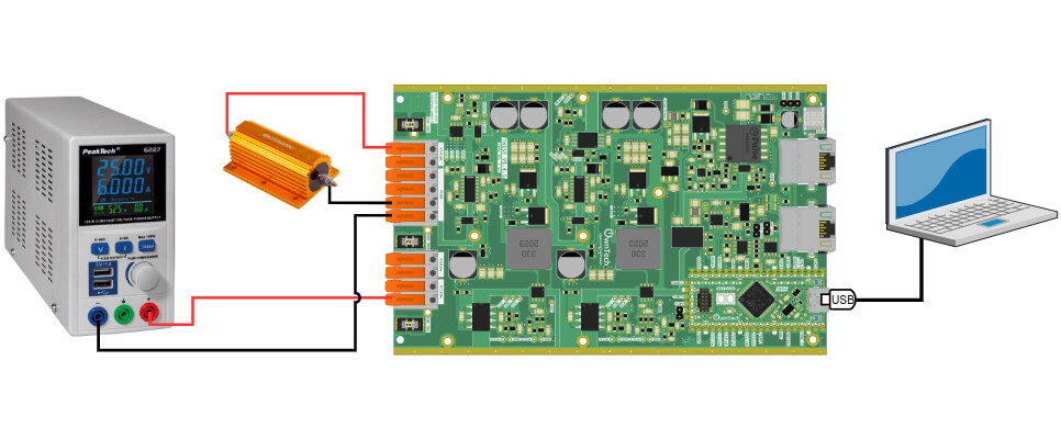
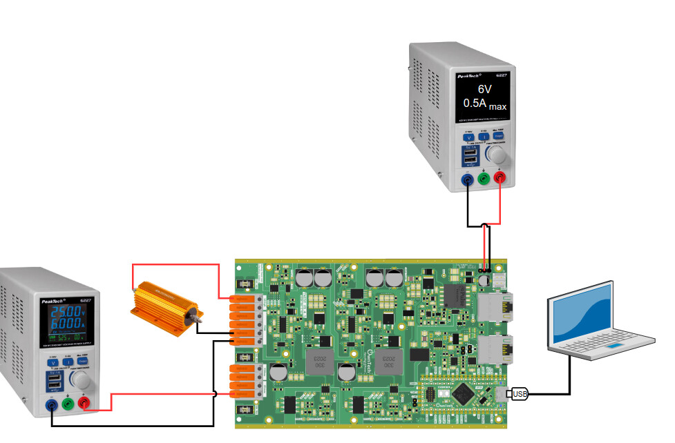
Step 1 : Make it work as is with a source on the low side and a resistor on the high side to validate that you can control the current of the boost (either i_high or i_low)
I just noticed something. In your diagram, you connect your battery to the mains via a twist board. Remember that the Twist board cannot be connected to the mains. It is not capable to handle the 230V.
Great! Do no hesitate to use draw.io to make your diagrams and then share the editable link. It is always easier to discuss and iterate over editable images.